Contents:
- Introduction
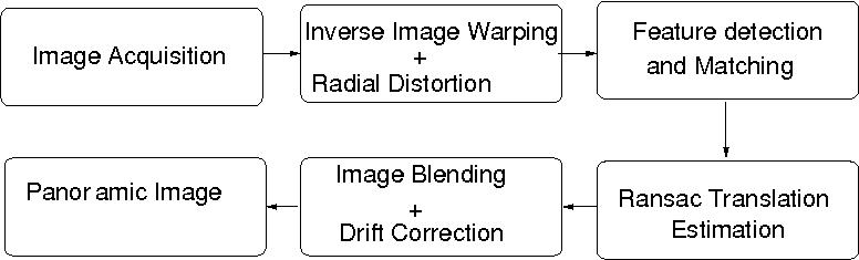
- Theory and Implementation Details
- Cylindrical Image Warping
- SIFT Feature Detections
- Ransac Translation.
- Post Processing:
- Image Blending
- Feathering Algorithm.
- Image Pyramid Algorithm.
- Drift Correction.
- Performance and Results
- Software usage.
- References.
Introduction
Generating full view panoramic images
is important for both commercial
and artistic value. Since the inception of photography many specific
devices have been invented to create panoramic images but with the
availability of inexpensive digital camera, the desire to create full
panoramic images is overwhelming and importance of automatic image
stitching is quite high.
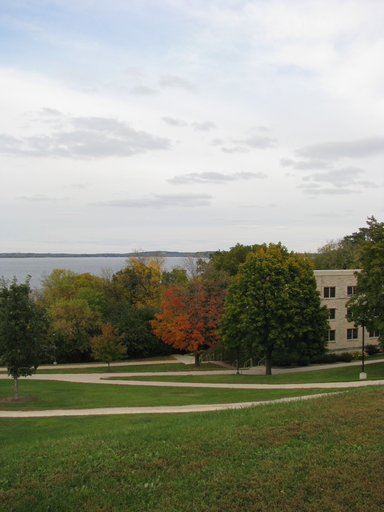
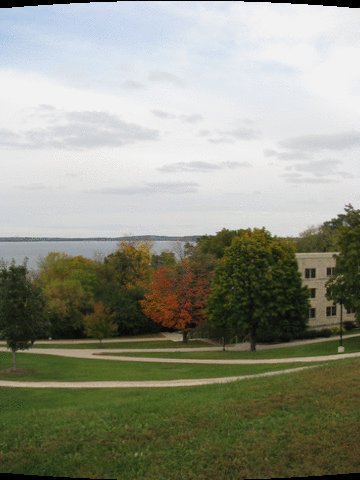
In this project, we create panoramic images using Cylindrical Warping. Cylindrical warping is easiest to implement, but it has stringent requirement that all the images must be taken with level camera or with the known tilted angle. With this method, full homography calculations are not needed only the translation along the angular direction is required to create the panoramic images.
In this project, we create panoramic images using Cylindrical Warping. Cylindrical warping is easiest to implement, but it has stringent requirement that all the images must be taken with level camera or with the known tilted angle. With this method, full homography calculations are not needed only the translation along the angular direction is required to create the panoramic images.
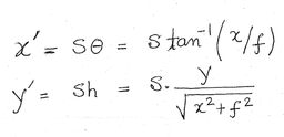
Forward Warping:
From image coordinates (x,y), the projected coordinates on the cylinder (x', y') are given by :
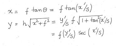
Inverse Warping:
inverse mapping from cylindrical
coordinates (x',y') to the image (x,y) is :
In forward warping the source image
is
mapped onto cylindrical surface, but it can create holes in the
destination
image ( because some pixels may never get mapped there). therefore we
use inverse mapping where each pixel in the destination image is mapped
to the source image. Since either of the mapping is unlikely to be
exact on the
pixel values, bilinear interpolation is used to calculate the colors at
the destination pixels.
Radial Distortion:
Because of the thick lens that are
often used in the camera, it is
necessary to correct the radial distortions in the image. One of
the simplified distortion model that is commonly used is
Xd = Xu( 1 + k1*r^2 + k2*r^4)
Yd = Yu( 1 + k1*r^2 + k2*r^4 )
Where (Xd,Yd) are the distorted image position and (Xu,Yu) are the undistorted correct position. The values (k1,k2) that depends on the camera can be calibrated using some standard techniques.
Both inverse mapping and radial distortion correction requires interpolation to calculate the color values at the destination pixel.o Interpolation is not only expensive, they also smooth the features, therefore, this step must be minimized to get high quality final images. In this application there are two places where interpolated values are required (1) Cylindrical to image in inverse warping (2) From undistorted image values to distorted images values. We can combine these two steps and calculate cylindrical image values directly from the distorted images and therefore, avoid the intermediate interpolation values.
 |
 |
SIFT Feature detection
We directly use SIFT algorithm to produce features in every image. Each SIFT descriptor is 128 char long. These features are matched with neighboring image to estimate the translation. Since there could be small number of outliers that has potential to misalign the final images, we use RANSAC algorithm to eliminate these outliers from the final estimation.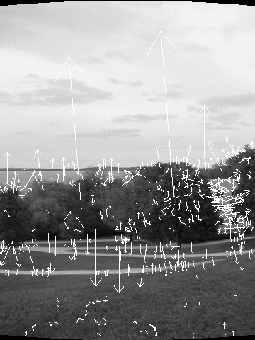
Ransac Translation
Ransac algorithm is general purpose
algorithm that can be used to
calculate full homography in the presense of outliers. The use of
cylindrical warping has the advantage that only the translation motion
has to calculated on the warped image. Also for the translation
estimation, only one feature is sufficient. Ransac estimation counts
the inliners based on some tolerance value ( d < eps) which depends
on the noise present in the images. Since our image capturing was high
quality, only two pixel tolerance was sufficient to get good
estimation. ( We found that that in our images only 5-10% outliers).
Image Blending:
When different images are stitched
together, for various reasons
(changed lighting conditions, vignette effects) the adjacent pixel
intensities differ enough to produce artifacts as shown in the
following pictures. To remove these artifacts, we experimented with two
algorithms (1) Feathering (2) Image pyramids.
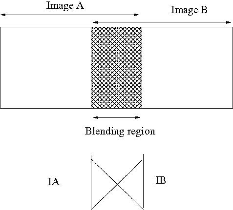
Feathering or center weighting image blending:
In this simplest approach, the the
pixel values in the blended regions
are weighted average from the two overlapping images. Sometimes this
simple approach doesn't work( for example in the presence of exposure
differences ). But in our case, all the images were taken at the same
time and using high quality tripods, therefore, this simple algorithm
produces excellant results.
PB(i,j) = (1-w)*PA(i,j) + w*PB(i,j)
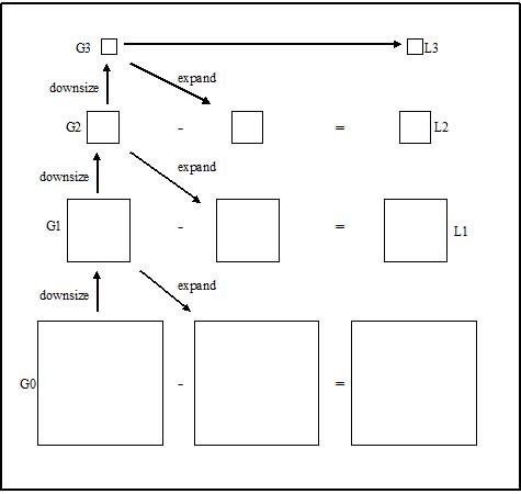
Pyramid Blening:
Laplacian pyramid is an algorithm using Gaussian to blend the image while keeping the significant feature in the mean time. It downsizes the image into different levels (sizes) with Gaussian. Later it expands the Gaussian in to the lower lever and subtracts from the image in that lever to acquire the Laplacian image.
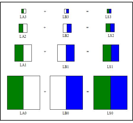
After generating Laplacian pyramids for the overlap images A and B, we combine the two images in different Laplacian levels by combining partial images from each of them.
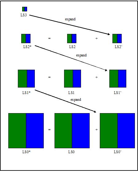
Afterward, we expand the LS from the top
level () to the next level (N-1) and add it to the original Laplacian
image in the corresponding layer () to generate the latest Laplacian
image in the corresponding layer (). We repeat this step until reaching
ground level () and the final result will be the blending image
 |
 |
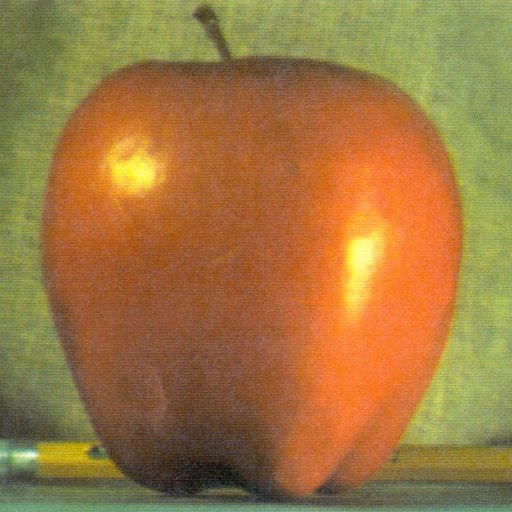
|
Apple (Image A) |
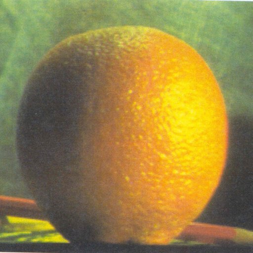
Orange (
Image B) |
 |
 |
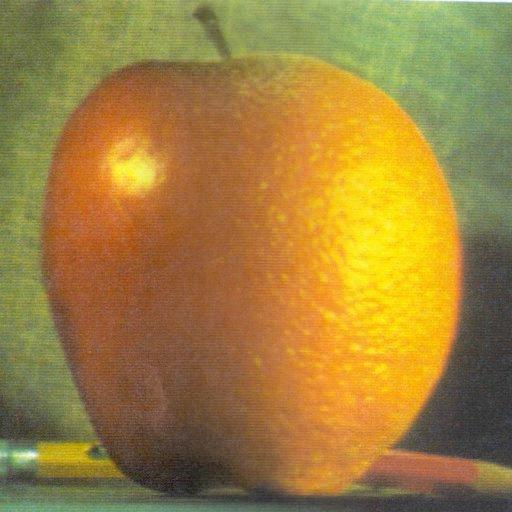
| Feathering
Blend |
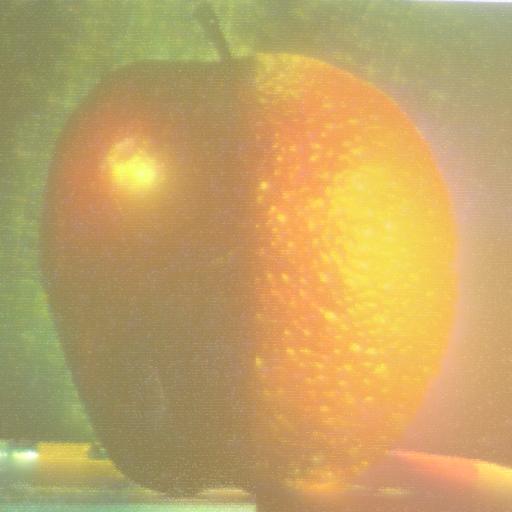
Laplace
Pyramid Blend |
Drift Correction:
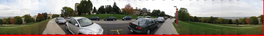
Very often the first image and the last image in the view don't align properly. This misalignment can be adjusted by shear warping and other bundle adjustment algorithm. In our case, we didn't have to do any adjustment as the misaligment was only 1-2 pixels.Results:
We used Canon SX100 and Kedan tripods provided by Dr. Li Zhang. Some specific information of the camera are as follows:resolution : 480x640
focal length : 678.05421
K1 : -0.22982
K2 : 0.22952
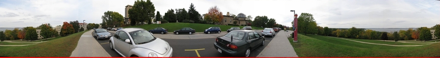
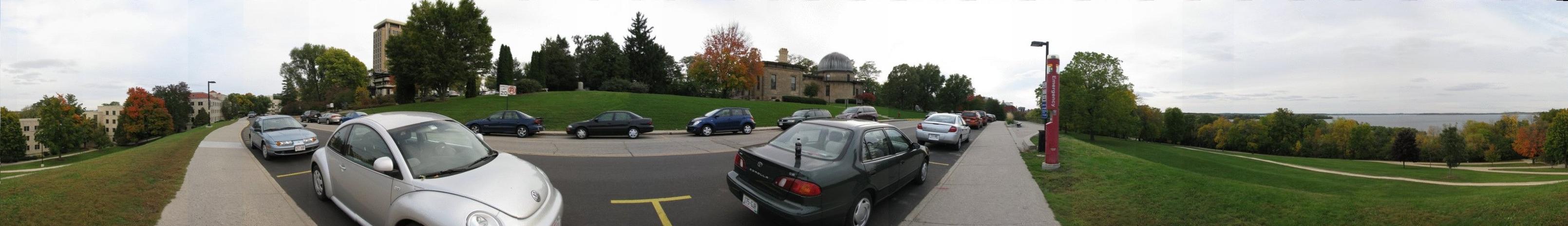
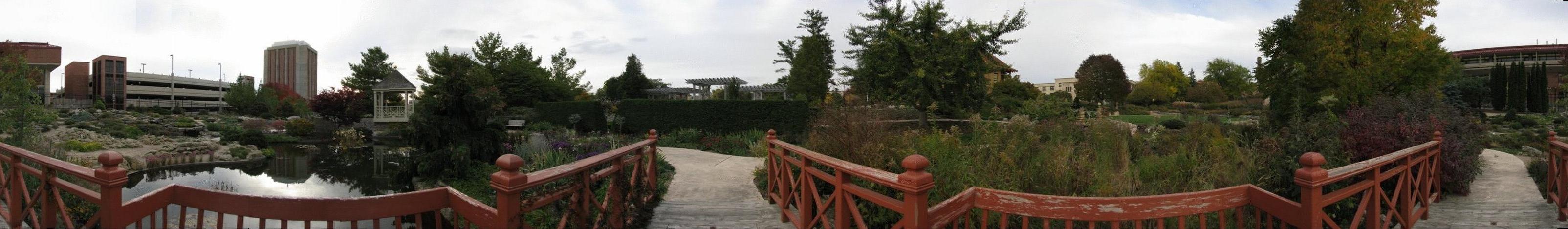
Here is the panoramic image generated from our implemention: panorama1 and panorama2
Software and Usage Guide:
The entire source code is written in C++. The only dependencies to use this software are "SIFT" and ImageiMagick++ which must be downloaded separately. Monju has developed Pyramid Blending code in MatlabClick here to download the entire source code.
Usage:
Step 1: Create one folder, set DataSet.
Step 2: Inside the Dataset folder create some new directories;
DataSet/RawImages : All the raw images goes in this directories
DataSet/WarpImages: All cylindrical warped images are stored in this directory.
DataSet/PNGImages : All cylindrical images are converted in gray scale for feature detection.
DataSet/Keys : All features keys from the Sift programs are stored in this directory.
Once all the directories are created execute the command
executable <root directory name>
It will generate a panormic image "panimage.jpg" which must be cropped using ImageMagick.
Reference software
References
- R. Szeliski and H.-Y. Shum. Creating full view panoramic image mosaics and texture-mapped models, SIGGRAPH 1997, pp251-258.
- M. Brown, D. G. Lowe, Recognising Panoramas, ICCV 2003.
Group Contribution
We worked as a group but distributed the work as follows:Chaman Singh : Develop the entire C++ code including warping, ransac, feathering (in C++) , results, performance analysis and
document writing.
MonJu : Image taking, Pyramid blending code in matlab, feathering code in matlab.