Design Viewpoint Editor is used to create special purpose "variations"
or "viewpoints" of a schematic. Viewpoints allow you to rapidly adjust
and maintain different sets of properties for your schematic independent
of the graphical drawing. You can maintain variations of a schematic without
having to go back and re-edit the drawing for each one.
Viewpoints allow you to save and maintain various experimental setups
for a schematic without having to create a new one for each experiment.
The use of viewpoints also allows several engineers to work with the same
schematic drawing concurrently without having to maintain multiple identical copies of it.
Design Viewpoint Editor can be used to set local properties
of parts in a schematic as well as global parameters which pertain
to the whole drawing. It can also be used to set up standard
configurations for using the drawing as input to other
design tools such as simulators and layout tools. Here we will use
Design Viewpoint Editor to set the parameters needed
to simulate our design using scn08hp standard cells for MOSIS fabrication.
This will be done by customizing a generic QuickSim simulation
viewpoint to work with the scn08hp library. The customization is
quite straightforward as it requires only the addition of one
primitive model and one electrical properties parameter.
For more details regarding primitives
and parameters, see Design Configuration Rules on page 2-4 of
the Design Viewpoint Editor User's and Reference Manual in the
INFORM database.
-
You first begin by invoking Design Viewpoint Editor either by
clicking on its icon in the Design Manager tools window or by
typing dve at the unix command line prompt. The application
window should appear similar to that shown in Figure 4.
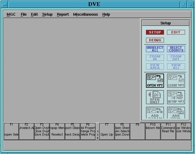
Figure 4: Design Viewpoint Editor Window.
-
Click on the OPEN VPT button, then open the navigator window.
Select the component you want to create a viewpoint of (in this case,
the 2-1 mux) and click OK.
-
In the Open Design Viewpoint dialog box, change the viewpoint name from
default to some easily recognized name. Use qsim_nom in this
example, since our intent is to simulate the circuit with nominal delays
for the logic gates. Click OK. Two windows will open, with one
having the name of the current viewpoint and the other titled
Design Configuration.
-
Even though we are targeting QuickSim II in this tutorial,
a variety of design tools can be used with your schematic. Each tool
has specific requirements for properties and values which are associated
with the components in the schematic. We will now start the viewpoint
setup for our scn08hp parts with the primitives and properties
needed for QuickSim. Select the standard setup
(Quick)SIM and Path from the Setup menu in the menu bar.
Another way to do this is to click on the SETUP VPT icon in
the Setup palette.
Your screen should now look something like
this
-
You will now customize the standard viewpoint with two additions.
First, you establish that any part having the model property value
of "technology" will be considered a primitive in the design hierarchy:
in other words, a leaf of the hierarchy tree.
From the Edit menu bar, select ADD -> PRIMITIVE, or,
simply click on the ADD PRIM icon in the Setup palette.
Enter the following values into the form which appears:
Name: model
Value: technology
Property Type: Expression
This also specifies that the property value "technology" will be
treated as an expression: in this case as a single variable expression
to be evaluated wherever it is specified. Click on OK when done.
-
You now need to specify a value for the variable parameter "technology"
which appears in the above model expression.
From the Edit menu bar, select ADD -> PARAMETER,
or simply click on the ADD PARAM icon in the palette. The
values required in this form are:
Name: technology
Value: scn08hp_nom
This tells DVE to give the variable parameter "technology" the value
"scn08hp_nom". Now when simulating from this viewpoint, the delay
properties associated with nominal operation of these cells will be used.
No further schematic editing needs to be done to enter gate delays,
because the "scn08hp_nom" delay tables which come with the cell
library will be used.
Your screen should now look like this.
-
Save the viewpoint by clicking on the SAVE DESIGN icon and exit DVE.
Alternatively, you can use the script
qsim_prep
for creating the Quicksim viewpoint with the specific setup for the scn08hp_nom
library of standard cells. In order to run this script, you have to
first add the directory in which it is located in your UNIX "path".
To create a viewpoint, then, just go to the directory where your logic
design is rooted, and run qsim_prep design_name, where "design_name"
is the name of your logic design. The name of the created viewpoint will be by default
qsim.vp.
You have now created a design viewpoint which attaches to the basic 2-1
MUX schematic all the necessary parameters for simulating the part using
scn08hp standard cell models under nominal delay conditions. This
standard library is also set up to simulate under worst case delay
conditions (set "technology" to "scn08hp_slow") and under best
case delay conditions (use "scn08hp_fast"). You may want to
create different viewpoints for each of these additional cases, or
simply edit the existing viewpoint using DVE. You may later want to consider
how you would set up a viewpoint to simulate different parts of the
same design using different delay conditions. For the moment, you are
ready to learn how to use QuickSim II in combination with a custom
design viewpoint to simulate the 2-1 MUX.