Interprocedural Analysis

Contents

Motivation

We need information about the effects of a procedure to propagate dataflow information across a call. For example:
    x=0;  
	// is y live here? (yes iff used in procedure P)
    call P();
	// is x still equal to 0 here? (yes iff not changed in P)
    y=x;
Note: sometimes this is not an issue, for example when we are tracking information only for non-aliased locals, and using call-by-value only.

We also need information about call sites to start dataflow analysis for procedures other than "main". For example:

    procedure P(int a, int b)
    { // what are the values of a, b, and globals here?
      .
      .
      .
      // what globals are live here?
      // if a and b are passed by reference, are they live here?
     }
The answers to these questions depend on what is true before/after the calls to procedure P (before for forward problems, and after for backward problems).

Note that pointers and reference parameters make it especially difficult to answer these kinds of questions. For example:

Reference parameters are actually implemented using pointers, so any solution that handles pointers can handle reference parameters, too. (One solution is to assume that a pointer can point to ANY memory location; another is to assume that it can point to any heap-allocated location, or to any stack location whose address is taken somewhere in the program. Pointer analysis can be used to narrow the possibilities further.) There are some approaches that handle reference parameters but not pointers in general. We will look at one such approach later; for now, we'll assume that the programs we deal with contain no pointers or reference parameters.

There are several possible approaches to handling programs with procedure calls; some address what to do for procedure entry/exit; some address what to do for a procedure call; some address both issues. We will look at the following approaches:

Approach 1 (use safe dataflow functions)

A simple way to deal with procedure calls is to do no special analysis, and to use safe dataflow functions for the entry/exit node of each procedure (the entry node for a forward problem, the exit node for a backward problem), and for every call node.

For example:

1. Dataflow functions for entry/exit nodes:

2. Dataflow functions for call node n:

Approach 2 (use the supergraph)

Another approach that requires no additional analysis involves converting the entire program to a single CFG (called a supergraph) by first building the CFGs for the individual procedures, then removing the edges out of all nodes that represent procedure calls, and finally adding edges as follows: We can now do normal dataflow analysis on this supergraph. For a forward problem, we would start at the enter node of "main"; for a backward problem, we would start at main's exit node.

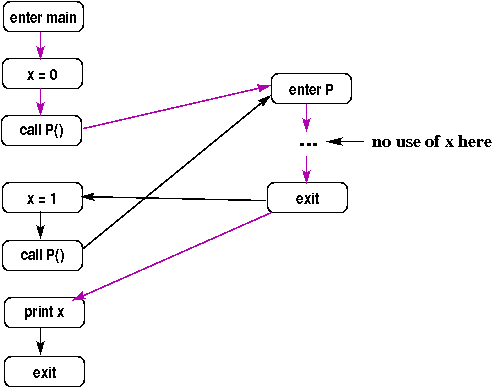
A problem with this approach is that it includes interprocedurally invalid paths: paths that correspond to a procedure being called from one call site but returning to another. This is bad because the results of the analysis will generally be less accurate (i.e., more conservative) than if the paths were restricted to include only interprocedurally valid paths (paths that go from a call site to the called procedure and back to the same call site). For example, the following shows a supergraph with an invalid path shown using purple edges (representing the first call to P returning to the second call site).

If we do normal live variables analysis on this supergraph, we will take this invalid path into account, and thus will conclude that x is live after the assignment "x=0" (while in fact it is not live there).

Approach 3 (use summary information)

An approach that does require additional analysis (before doing our usual dataflow analysis on the CFGs for each procedure) involves using summary information about each procedure to determine a safe (conservative) dataflow function for every call node. Typically, summary information tells what variables might be modified and might be used by each procedure. Since we are assuming no reference parameters, this means the set of globals that might be modified, and the set of globals and formals that might be used.

Example

Assume we know that procedure P may modify globals x and y, and may use globals y and z. Below are the dataflow functions we would use for node n, a call to P, for several dataflow problems.

Dataflow Problem Dataflow Function for Call Node n
reaching definitions fn(S) = S U {(x,n),(y,n)}
live variables fn(S) = S U {y,z}
constant propagation fn(S) = S - ((x, *), (y, *))

Notes:

  1. For reaching definitions, we cannot assume that the procedure call kills anything (because all we know is that procedure P may modify x and y). Similarly, for live variables, we cannot assume that the call "kills" any variables.
  2. If we know that P might use its first formal parameter, and the call at node n is: P(a, b), then the dataflow function for live variables must also add "a" to the given set.
Note that this approach only addresses the question of how to handle a call node; it doesn't help with the problem of determining what dataflow facts hold at the start/end of a procedure.

The summary information that we want to compute for each procedure P is:

Below we will consider how to compute this information; first for global variables only, then for globals and value parameters, then for globals, value parameters, and reference parameters.

Globals Only

Initially, we will assume that the program we're analyzing has:

Therefore, for now we only care about the globals that might be modified/used by each procedure (we will relax the assumption about parameters later).

Step 1: Compute IMOD and IREF

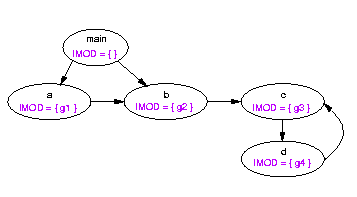
Step 2: Build the call graph

Step 3: Collapse cycles.

Step 4: Compute GMOD and GREF.

For each node n, GMOD(n) and GREF(n) are the dataflow facts that hold before node n (i.e., n.GMODBefore and n.GREFBefore).

Value Parameters

Now let's relax our initial assumption that there are no parameters, and consider procedures with value parameters. In this case, the computation of GMOD sets will not change, but the computation of GREF sets must change. (We want to consider a call like p( x ) a use of x iff p might use the corresponding formal, so we need to take formal parameters into account when computing GREF sets).

Step 1: Compute IREF sets as before, but include local variables and formal parameters.

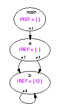
Step 2: Build the call graph, but this time include one edge for every call site (so there can be multiple edges between pairs of nodes). For example, here's a program:

void main() {         void a( f1 ) {           void b( f2, f3 ) {
s1: call a(v1);	      s2: call b(v2, v3);          print f3;
}                     s3: call b(v4, v5);      s4: call b( g1, g2 );
                                               }
And here is the corresponding call (multi)graph, with IREF sets (graph edges are labeled with the corresponding call site):

Step 3: Compute GREF sets for each node n and for each callsite s as the greatest fixed point of the following set of equations:

GREF(n) = (union of all GREF(s) such that s is a call site in n) U IREF(n)
GREF(s) = GREF(called node m) with all formals mapped back to the corresponding actuals
This can be done by initializing all of the nodes' GREF sets to their IREF sets, and all of the call sites' GREF sets to empty, putting all nodes and call sites on a worklist, and iterating until the worklist is empty. Each time a node n is removed from the worklist, its current GREF set is computed. If that set doesn't match its previous value, then all of the call sites that call n are added to the worklist (if not already there). Similarly, each time a call site s is removed from the worklist, its current GREF set is computed. If that set doesn't match its previous value, then the node that contains s is added to the worklist (if not already there).

For the running example, the final values are:

node or call site GREF set
maing2
a g2, v3, v5
b f3, g2
s1 g2
s2 v3, g2
s3 v5, g2
s4 g2

Reference Parameters

Finally, let's think about what happens when we allow reference parameters. In a sense, this introduces two problems:

  1. The IMOD/IREF sets are not complete because of aliases:
    void a( f1, f2 ) {
        f1 = f2 + 1;
    }
           
    In this example, f1 and all of its aliases are modified; f2 and all of its aliases are used. The aliases can include globals (due to a call like: a( g1, g2 )) or other formals (due to a call like: a( x, x )).

    Similarly, any def/use of a global is actually a def/use of the formals to which it is aliased, too.

  2. Since a procedure's IMOD/IREF sets are not complete, neither are its GMOD/GREF sets, which means that incomplete information is propagated to its callers. For example, here is a call graph in which each node represents one procedure, the code for that procedure is given in the node, and the IMOD and GMOD sets that would be computed using a straightforward extension of the algorithm used above for value parameters, are shown to the right:
      +-------------+
      | void main() |  IMOD = { }
      | call a( g ) |  GMOD = { g }
      +-------------+
            |
            v
      +--------------+
      | void a( f1 ) |  IMOD = { }
      | call b( f1 ) |  GMOD = { f1 }
      +--------------+
            |
            v
      +--------------+
      | void b( f2 ) |
      | f2 = 0       |  GMOD = IMOD = { f2 }
      +--------------+
      
    Note that in b, f2 is aliased to g, so b actually modifies g as well as f2; this is an example of problem 1, discussed above. However, since b does modify g (due to the call from a), it is also true that a modifies g. Yet g is not in GMOD(a). This is the example of problem 2.
Surprisingly, it has been shown (by Banning in 1979) that GMOD/GREF sets can be computed correctly in the presence of reference parameters by breaking the computation into separate phases:
  1. Compute DMOD/DREF: modify/use sets that ignore the effects of aliasing due to reference parameters (essentially the GMOD/GREF sets computed by the algorithm discussed above for value parameters).

  2. Compute alias sets for all formal parameters and all globals on a per-procedure basis:
    • Alias(f,p) = {x | x is a formal of p or a global, and is aliased to f}
    • Alias(g, p) = {x | x is a formal of p and is aliased to g}
  3. Combine the results of (1) and (2) to determine:
    • What each call may actually define/use (transitively)
    • What each def/use of a formal f or a global g may actually define/use.

Computing DMOD and DREF

The computation of DMOD/DREF is similar to the method for computing GMOD/GREF given only value parameters; i.e., dataflow functions go on the edges of the call (multi)graph, and IMOD/IREF sets are propagated back across those edges, replacing formals with actuals. Here is an example; the values shown on the edges are the actuals of the calls that are modified by the called procedure (i.e., the corresponding formals are in the called procedures' IMOD or DMOD sets):
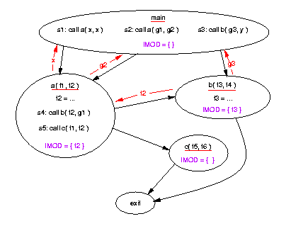
The DMOD sets are:
s1:   { x }
s2:   { g2 }
s3:   { g3 }
s4:   { f2 }
s5:   { }
main: { x, g2, g3 }
a:    { f2 }
b:    { f3 }
c:    { }

The next step is to compute the alias sets. This has been described in the paper "Fast Interprocedural Alias Analysis" by Keith Cooper and Ken Kennedy, published in the Conference Record of the Sixteenth Annual ACM Symposium on Principles of Programming Languages (1989).

Alias sets can be computed in two steps:

  1. Use the "binding graph" to compute formal/global aliases.
  2. Use the "pair binding graph" to compute formal/formal aliases.

The binding graph for a program includes a node for each formal of each procedure, and an edge f1 → f2 iff f1 is passed as an actual parameter in some call to p, and f2 is the corresponding formal of p. For example, at call site s4 in procedure a of the program shown above, f2 is the 1st actual, and f3 is the corresponding formal of the called procedure b. Therefore, in the program's binding graph there would be an edge f2 → f3. Here is the complete binding graph for the example program:

To compute the formal/global aliases (for each formal f, which globals it may be aliased to):

// collapse scc's of binding graph
   replace each scc with a representative node n

// initialize
   for each node x, set A(x) = {}
   for each call site s
      for each global v passed to formal f at s
         A(f) = A(f) U { v }  // if f was in an scc, use the rep. node n for f

// traverse the graph, propagating aliases
   for each node f in topological order
      A(f) = A(f) U A(g) such that g is a predecessor of f

// set values for all nodes of scc's
   for each scc c
      for each node f in c
         let n be c's representative node in
	    A(f) = A(n)
For our example, after the initialization step, we'd have the following initial alias sets
A(f1) = { g1 }
A(f2) = { g2 }
A(f3) = { g3 }
A(f4) = { g1 }
A(f5) = { }
A(f6) = { }

The propagation loop would add g2 to the sets of f3 and f6, and would add g1 to the set of f5.

Note that this algorithm maps formals to the globals to which they are aliased (f1 → {g1}, etc.). We also want the sets "Alias(g,p) = the set of p's formals to which g is aliased in p". We can get those sets using this algorithm:

After using this algorithm in our example, we get:
Alias(g1, a) = { f1 }    Alias(g1, b) = { f4 }    Alias(g1, c) = { f5 }
Alias(g2, a) = { f2 }    Alias(g2, b) = { f3 }    Alias(g2, c) = { f6 }
Alias(g3, a) = { }       Alias(g3, b) = { f3 }    Alias(g3, c) = { }

Now we need to compute the formal/formal aliases. This is done using the "pair binding graph".

There are 3 different ways two formals can be aliased:

  1. The same actual is passed to two formals:
    +----------------+
    | call a( x, x ) |
    +----------------+
            |
    	v
    +-------------------+
    | enter a( f1, f2 ) |           f1 and f2 are aliased in a
    +-------------------+
    
  2. Global g is passed to one formal, an alias of g to another:
    +-------------+
    | call a( g ) |
    +-------------+
            |
    	v
    +-----------------+
    | enter a( f1 )   |
    | call b( f1, g ) |
    +-----------------+
            |
    	v
    +-------------------+
    | enter b( f2, f3 ) |           f2 and f3 are aliased in b
    +-------------------+
    
  3. Formals f1 and f2 are aliases, and are both passed as actuals.
           ...
            |
    	v
    +---------------------+
    | enter a( f1, f2 )   |
    | call b( x, f1, f2 ) |
    +---------------------+
            |
    	v
    +-----------------------+
    | enter b( f3, f4, f5 ) |       f4 and f5 are aliased in b
    +-----------------------+
    
So to identify aliased formals, we must: This is done using the "pair binding graph", which has one node for each pair of formals of the same procedure, and an edge (f1, f2) → (f3, f4) iff there is a call that passes f1 to f3 AND passes f2 to f4, or that passes f1 to f4 AND passes f2 to f3.

Here is the pair binding graph for our example program:

Once this graph is created, we identify "initial alias pairs" (formals that are aliased either because the same actual is passed twice, or because a global and its alias are passed as actuals) as follows:
for each call site s
   if var x is passed to two formals f1 and f2
   then {
         // same actual passed twice:
         //       call p(x, x)
         //              |  |
         //              v  v
         //       void p(f1,f2)
      mark (f1,f2)
   }
   for each actual f that is a formal of the procedure containing s
       let f' be the corresponding formal of the called procedure in
	  for each global g in A(f) that is passed as an actual at s
	      // global and its alias passed
	      //     call p(f, g)
	      //            |  |
	      //            v  v
              //     void p(f',f'')
	         let f'' be the corresponding formal in the called procedure in
		     mark (f', f'')
                             
In our running example, only the pair (f1, f2) is marked, because of the call "a(x, x)" in main.

The next step is to propagate the initial alias pairs by marking all nodes reachable from a marked node. This can be done as follows:

In our running example, node (f5, f6) would be marked (i.e., the initial alias of f1 and f2 would be propagated to f5, f6, due to the call at call site s5).

Note that if, in the end, a pair (fj, fk) is marked, it means that fj and fk may be aliased.

The final step in computing formal's aliases is to combine the results computed using the binding graph (which globals each formal is aliased to) with the new results computed using the pair binding graph (which other formals each formal is aliased to):

Here are the final Alias sets for all globals and formals:
Alias(f1, a) = { g1, f2 }    Alias(f1, b) = { }           Alias(f1, c) = { }
Alias(f2, a) = { g2, f1 }    Alias(f2, b) = { }           Alias(f2, c) = { }
Alias(f3, a) = { }           Alias(f3, b) = { g2, g3 }    Alias(f3, c) = { }
Alias(f4, a) = { }           Alias(f4, b) = { g1 }        Alias(f4, c) = { }
Alias(f5, a) = { }           Alias(f5, b) = {  }          Alias(f5, c) = { g1, f6 }
Alias(f6, a) = { }           Alias(f6, b) = {  }          Alias(f6, c) = { g2, f5 }
Alias(g1, a) = { f1 }        Alias(g1, b) = { f4 }        Alias(g1, c) = { f5 }
Alias(g2, a) = { f2 }        Alias(g2, b) = { f3 }        Alias(g2, c) = { f6 }
Alias(g3, a) = {  }          Alias(g3, b) = { f3 }        Alias(g3, c) = { }

Once alias information is known, we can use it to compute GMOD sets for every call site and for every procedure:

For our example:
           DMOD             Aliases                           Final GMOD

GMOD(s1) = { x }             ---                              { x }
GMOD(s2) = { g2 }            ---                              { g2 }
GMOD(s3) = { g3 }            ---                              { g3 }
GMOD(s4) = { f2 } U Alias(f2, a) = { f2 } U { f1, g2 } =      { f1, f2, g2 }
GMOD(s5) = { }

GMOD(main) = { x, g2, g3 }   ---                              { x, g2, g3 }
GMOD(a)    = { f2 } U Alias(f2, a) = { f2 } U { f1, g2 } =    { f1, f2, g2 }
GMOD(b)    = { f3 } U Alias(f3, b) = { f3 } U { g2, g3 } =    { f2, f3, g3 }
GMOD(c)    = { }             ---                              { }
Note that GMOD(a) does not include g1 even though a modifies f2 and f2 may be aliased to f1, and f1 may be aliased to g1. The reason is that those two aliases occur on different calls to a, so their effects are not combined (and this is correctly reflected in the computed GMOD set)!

Note also that for dataflow analysis, it is the call site GMOD sets that we would use to define the dataflow function for a call node, not the called procedure's GMOD set (because the GMOD set for the call site tells what may be modified as a result of that particular call, rather than what might be modified by the called procedure on some call).

Computing Summary Information

The Sharir and Pnueli Approach (Using Phi functions)

The ideas presented here are from a paper called "Two Approaches to Interprocedural Analysis", by Micha Sharir and Amir Pnueli, in a book called Program Flow Analysis, Theory and applications (edited by S. Muchnick and N. Jones).

The paper makes the following assumptions:

The ideas behind the approach defined by Sharir and Pnueli are as follows; given a program (a set of CFGs) and a (forward) dataflow problem of interest:

Note that PHI functions are better than jump functions, because they take into account what actually happens in called procedures, while jump functions treat calls safely but pessimistically.

How to use PHI Functions to Solve a Dataflow Problem

As mentioned above, once we have the PHI functions for all CFG nodes, we can solve a (forward) dataflow problem by computing the dataflow fact n.val for each CFG node n as follows:

enter-main.val = "init"
for each procedure p:
                   _                                  _
    enter-p.val = | | c.val            // the symbol | | means "meet"
		  c is a call to p

    n.val = PHIenter p, n (enter-p.val)

Note: If the program is not recursive, then these equations can be solved in one pass using a topological ordering of the call graph. If the program is recursive, then these equations will be recursive, too. In particular, for a recursive procedure p, enter-p.val will depend on a set of values c.val, and at least some of those will depend on enter-p.val. In this case, the greatest fixed point solution can be found using the usual iterative method:

Since it is only the enter and call nodes whose equations are mutually recursive, we can compute the dataflow solutions for those nodes first (using the iterative algorithm given above), then use the values computed for the enter nodes to compute the dataflow solutions for all the rest of the nodes (with no iteration).

Here is an example program (two CFGs):

          enter main                          enter p
               |                                 |
	       v				 v
	    1: x = 0                           7: if...
	       |                                 |  \
	       v				 |   v
	    2: call p()                          | 8: x = 3
	       |                                 |  /
	       v				 v v
	    3: x = 2                           9: exit
	       |
	       v
	    4: call p()
	       |
	       v
	    5: exit
And here are the PHI functions and final results we'd like to compute for reaching-definitions analysis:
CFG node PHI function Dataflow fact
enter main PHI(S) = S {}
1 PHI(S) = S {}
2 PHI(S) = S-(x,*) U {(x,1)} (x,1)
3 PHI(S) = S-(x,*) U {(x,1),(x,8)} (x,1)(x,8)
4 PHI(S) = S-(x,*) U {(x,3)} (x,3)
5 PHI(S) = S-(x,*) U {(x,3),(x,8)} (x,3)(x,8)
enter p PHI(S) = S (x,1)(x,3)
7 PHI(S) = S (x,1)(x,3)
8 PHI(S) = S (x,1)(x,3)
9 PHI(S) = S U {(x,8)} (x,1)(x,3)(x,8)
NOTE: If all paths (not just interprocedurally valid paths) were taken into account, the dataflow fact at node 5 would also include (x,1).

How to Compute PHI Functions

The PHI functions are defined using the following equations:

  1. For all procedures p (including main), the PHI function for the enter node (i.e., PHIenter p, enter p) is the identify function.
  2. For all non-enter nodes n in p, the PHI function for node n is the meet over all CFG predecessors m of n of the composition of two functions: hm,n and PHIenter p,m, where hm,n is defined to be:
      PHIenter q, exit q // if m is call q
      fm,n // otherwise
    where fm,n is the dataflow function on the CFG edge m→n.

Here is the example program again; each CFG edge is annotated with the dataflow function for reaching-definitions analysis ("id" is used when the function is the identity function):

          enter main                          enter p
               |                                 |
	       | id				 | id
	       v				 v
	    1: x = 0                           7: if...
	       |                                 |  \
	       | f(S)=S-(x,*) U (x,1)	      id |   \ id
	       v				 |    v
	    2: call p()                          | 8: x = 3
	       |                                 |  /
	       |				 | / f(S)=S-(x,*) U (x,8)
	       v				 v v
	    3: x = 2                           9: exit
	       |
	       | f(S)=S-(x,*) U (x,3)
	       v
	    4: call p()
	       |
	       v
	    5: exit
And here are the equations for the PHI functions for the example program above; in the following table, "o" means function composition, and "(f o g)(x)" -- i.e., f composed with g applied to x -- means "f(g(x))".

We can compute the PHI functions as the greatest solution to this set of equations using the usual iterative approach:

(Note that even if the program is not recursive, the equations will be mutually dependent if there are any loops in the program.)

In order to compute the PHI functions we need the following properties:

In order to satisfy the requirement about being able to compare functions for equality, we need a "canonical" representation for the functions, and we need to define the meet and the composition of two functions so that the result is in that canonical form.

One example where this can be done is Gen/Kill dataflow problems, in which the meet is set union. In this case, all dataflow functions are of the form:

where the Kill and Gen sets for each dataflow function are constants (since we're now putting dataflow functions on CFG edges, the Kill and Gen sets for fn→m would be defined in terms of the node n that is the source of the edge; i.e., they would be Kill(n) and Gen(n)).

Here's how we can define f1 meet f2 so that the results are in that same form:

Note that K1, K2, G1, and G2 are all constants, so we can compute: thus putting the final function back into canonical form: (S - K) U G).

And here's how we can define function composition for Gen/Kill functions so that the result is in canonical form:

Again, we can evaluate (K2 U K1) to get a new Kill set K, and ((G2-K1) U G1) to get a new Gen set G, so the final version is in canonical form: S-K U G.

Putting this all together, let's compute the PHI functions for the example program. Initially, the PHI functions for the two enter nodes would be the identity function. For all other nodes, it would be the top function: f(S) = {} (since the meet for reaching definitions is set union, the top value in the lattice is the empty set; the top function is the constant function that just returns the top value).

All of the non-enter nodes would be on the worklist. Assume that we choose node 1 first. Its equation is:

The PHI function for enter main is the identity function, so node 1's new PHI function is also the identity function (which is different from its previous value, the top function). Its successor, node 2, is already on the worklist. Assume we choose it next. Its equation is: and since PHIenter main, 1 is currently the identity function, this is just: We could also have computed this using our definition of function composition. In that case we would have defined the following sets: And computed the composition like this:

Suggestion: work this example through to the end. Make sure your results match the PHI functions given above.

Summary

To solve a dataflow problem using PHI functions, perform the following steps:

  1. Create a CFG for each procedure, with dataflow functions on the edges.
  2. For each CFG node n in procedure p, define the equation for n's PHI function. If n is "enter p", then PHIenter p, n is the id function. Otherwise, PHIenter p, n involves taking the meet of a set of functions, one for each CFG predecessor m of n. Each m contributes one function to the set; that function is itself the composition of two functions: If m is "call q", then the two functions are PHIenter q, exit q and PHIenter p, m. Otherwise, the two functions are fm→n (the dataflow function on the edge from n to m) and PHIenter p, m.
  3. Compute all PHI functions as the greatest solution to the set of equations defined in step 2.
  4. Use the PHI functions to solve the dataflow problem: If the program is not recursive, then process the procedures in topological order (on the call graph). To process a procedure p:
    • First set the value of p's enter node.
    • Then, for each node n in p, set n.val = n's PHI function applied to the value of p's enter node.
    Note that, for main, enter-main.val = "init", while for every other procedure p, enter-p.val is the meet of all c.val such that c is "call p" (since we're processing procedures in topological order, when we process procedure p, all nodes "call p" will already have been processed).

    If the program is recursive, then use worklist iteration to set the values of all enter and call nodes, then, for each non-enter, non-call node, compute n.val by applying n's PHI function to its procedure's enter node's value.

The Reps/Horwitz/Sagiv Approach: Reachability in the Exploded Supergraph

Overview

This approach is discussed in the paper
Precise Interprocedural Dataflow Analysis via Graph Reachability T. Reps,  S. Horwitz, and M. Sagiv. The technique applies to all "IFDS" problems, which are defined as follows:
I:
interprocedural
F, S:
for every program there is a finite set S, the dataflow facts are subsets of S, and the meet is set union or intersection.
D:
all dataflow functions are distributive.

Dataflow problems that fit in this framework include the following:

In what follows, we will assume that the programs to be analyzed do not include reference parameters or pointers. Handling those features is really an orthogonal problem; if appropriate alias analysis is done so that dataflow functions that satisfy the IFDS restrictions can be defined, then the graph-reachability approach can handle programs with those features.

We will also always use set union as the meet operation. Intersection problems are "must" problems, and are handled by solving the dual "may not" problem. For example, to solve the "must be garbage" problem, we would solve the "may not be garbage" problem. If a variable v is not in the "may not be garbage" set at a CFG node n, then v must be garbage at n.

Example

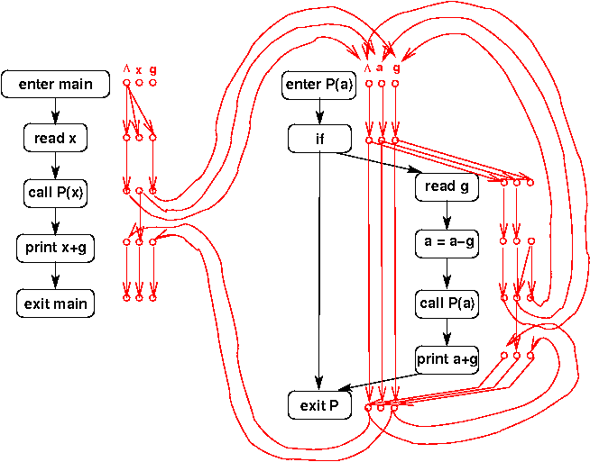
Below is an example "exploded supergraph" for the "may be garbage" problem.

The usual supergraph is shown in black (the inter-procedural edges have been omitted; the picture is complicated enough!). The "exploded" part of the graph is shown in red. Each CFG node has an associated set of red "exploded" nodes: one for each visible variable (local x and global g in main; formal a and global g in P) plus a special red node labeled Lambda. The red edges in the exploded graph represent the dataflow functions, with one dataflow function for each supergraph edge.

For example, this is the piece of the exploded graph associated with the edge from "enter main" to "read x":

The dataflow function associated with that edge sets all of the variables to "may be garbage"; i.e., the dataflow function is:

In general, there is an edge in the exploded supergraph from a Lambda node to a node d when the corresponding dataflow function puts d in the result regardless of the value of its argument, S (and there is always an edge from Lambda to Lambda). Similarly, there is an edge from d to d, like this:

when d is in the result if it is in S. An edge from x to g like this:

means that g is in the result if x is in S, and edges from both x and g to g:

mean that g is in the result if either x or g is in S. (Note that in the above 3 examples, the Lambda-to-Lambda edges were omitted for clarity, but they would actually be in the exploded graphs.)

Now look at the two calls to P in the supergraph. The dataflow functions for the intra-procedural edges out of the two call nodes reflect the fact that a procedure call cannot change the values of local variables (so in main, variable x is garbage after the call iff it was garbage before the call, and similarly for formal a in procedure P). The dataflow functions for the inter-procedural edges out of the two call nodes (those edges are not shown in the figure) reflect the fact that the value of formal parameter a at the start of P has the value of the corresponding actual parameter.


TEST YOURSELF #1

Assume that we are creating the exploded supergraph for a procedure with three local variables: x, y, and z. Draw the graphs that represent the following dataflow functions:

  1. f(S) = {y}
  2. f(S) = S
  3. f(S) = S - {x, y}
  4. f(S) = S union {x}
  5. f(S) = if (x is in S) then S union {y} else S - {y}

The exploded graph is used to solve the dataflow problem that it represents by finding all valid paths (paths that respect procedure call/return pairings) that start from the Lambda node associated with enter main. If an exploded-graph node d at CFG node n is reachable from "enter-main, Lambda", then d is in the dataflow fact at n (recall that a dataflow fact is always a set, because we are working with an IDFS problem). For example, in the exploded supergraph given above, there is a valid path from "enter-main, Lambda" to "print x+g, g" (by taking the left branch out of the if node in procedure P). This tells us that global g may be garbage at that point. This is correct: if the left branch of the if in procedure P is taken, global g is never assigned a value.

The reason for using valid-path reachability in the exploded supergraph to determine what values are in the dataflow facts at each CFG node is that a path in the exploded graph represents the composition of dataflow functions. If exploded-graph node "n, d" is reachable from "enter-main, Lambda", then there is a path in the CFG whose composed dataflow functions put d in the result at node n. Since the meet operation is set union, this means that d is in the meet over all valid paths solution at n.

Algorithm Key Ideas

Here are the key ideas for doing dataflow analysis using the exploded supergraph:

  1. Represent each CFG edge's dataflow function as a graph.
  2. Create the exploded supergraph by "pasting together" the function graphs.
  3. The exploded graph node d at CFG node n represents d being in n's "before" set.
  4. Graph node d actually is in that set iff it is reachable from exploded-graph node "enter-main, Lambda" via a valid path.
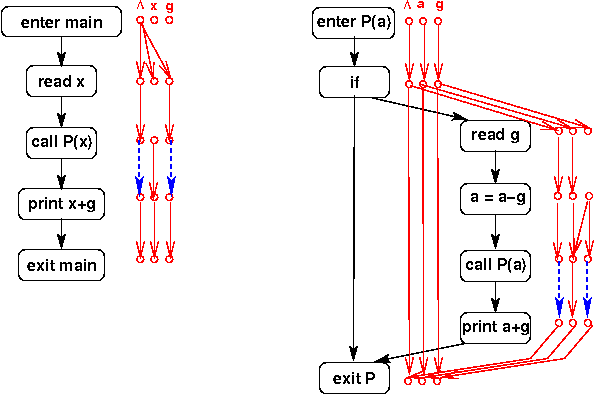
The one missing part of the algorithm is how to do valid-path reachability in the exploded supergraph. That is done by computing and adding summary edges across calls in the exploded graph. A summary edge represents the transitive effects of a call: i.e., there is a summary edge d1 → d2 at a call to procedure P iff there is a valid (interprocedural) path from "enter P, d1" to "exit P, d2". Actually, that path will be from the node in P's supergraph that is the target of the interproceduraledge out of d1, to the node that is the source of the interprocedural edge out of exit P back to the node after the call. The exploded supergraph given above is repeated below, this time with summary edges instead of interprocedural exploded-graph edges. The summary edges are shown as dashed, blue arrows.

Once summary edges are in place, valid-path reachability is done as follows:

How to Compute Summary Edges

Consider the procedure call shown below, where variables g1, g2, and g3 are all globals.

A summary edge is added from the exploded-graph node "call-P, g1" iff there is a valid path in the exploded supergraph for procedure P from "enter-P, g1" to "exit-P, g1". And similarly for the other exploded-graph nodes associated with "call P".

An algorithm that finds such paths is given in the paper. The idea is to start from "enter-main, Lambda" and to keep track of all exploded-graph nodes reachable via valid paths from there. If we find that an exploded-graph node d1 associated with "call P" is reachable, then we start up a similar search from "enter-P, d2", where d2 is d1's inter-procedural successor.

Whenever we find a valid path from "enter-P, d1" to "exit-P, d2", we add a corresponding summary edge across all calls to P. For example, in the picture of our running example above that includes the blue summary edges, the summary edge out of "call-P, g" was added (to both calls to P) because (a) there is a valid path from "enter-main, Lambda" to "call-P, g" (which started up a search for all nodes reachable in P from "enter-P, g"), and (b) there is a valid path in P from "enter-P, g" to "exit-P, g" (taking the left branch out of the if).