Project 3: Photometric Stereo
Shengnan Wang
Date: 10/23/2007
Introduction:
The goal of this
project is to implement a system to construct a height field from a series of
images of a diffuse object under different point light sources. The software is
able to calibrate the lighting directions, find the best fit normal and albedo at each pixel, find a surface which best matches the
solved normals and finally reconstruct the surface of
the object.
Approach:
1.
Calibrate lighting directions.
One method of
determining the direction of point light sources is to photograph a shiny
chrome sphere in the same location as all the other objects. Since we know the
shape of this object, we can determine the normal at any given point on its
surface, and therefore we can also compute the reflection direction for the
brightest spot on the surface.
- Compute the centroid of the ball mask as the center of the ball
- Compute the
average distances between the boundary pixels to the center as the radius
- Compute the centroid of the highlight pixels in each lighting
image and its distance from the center of the ball, get ( Xp, Yp, sqrt(radius
* radius �C Xp * Xp �CYp * Yp)), vector N is the normal vector of the ball
at point P, equals to OP/R (OP is the vector from the center
of the ball to point P)
- Light direction L = 2*(N dp R) * N �C R (dp is doc product)
2. Normals from Images.
The appearance of diffuse objects can be
modeled as ![]() where
I is the pixel intensity, kd
is the albedo, and L is the lighting direction (a
unit vector), and n is the unit surface normal. (Since our images are already
balanced as described above, we can assume the incoming radiance from each
light is 1.) Assuming a single color channel, we can rewrite this as
where
I is the pixel intensity, kd
is the albedo, and L is the lighting direction (a
unit vector), and n is the unit surface normal. (Since our images are already
balanced as described above, we can assume the incoming radiance from each
light is 1.) Assuming a single color channel, we can rewrite this as ![]() so
the unknowns are together. With three or more different image samples under
different lighting, we can solve for the product
so
the unknowns are together. With three or more different image samples under
different lighting, we can solve for the product ![]() by
solving a linear least squares problem. The objective function is:
by
solving a linear least squares problem. The objective function is:
![]()
To help deal with shadows and noise in
dark pixels, its helpful to weight the solution by the
pixel intensity: in other words, multiply by Ii:
![]()
The objective Q is then minimized with
respect to g. Once we have the vector g = kd
* n, the length of the vector is kd and the
normalized direction gives n.
I have weighted each term by the image
intensity which will reduce the influence of shadowed regions.
3. Solving for color albedo.
Recall the objective function is
![]()
To minimize it, differentiate with
respect to kd, and set to
zero:
![]()
![]()
Writing Ji = Li . n, we can also write this more
concisely as a ratio of dot products: ![]() This can be done for each channel
independently to obtain a per-channel albedo.
This can be done for each channel
independently to obtain a per-channel albedo.
4.
Least square surface fitting.
If the normals
are perpendicular to the surface, then they'll be perpendicular to any vector
on the surface. We can construct vectors on the surface using the edges that
will be formed by neighbouring pixels in the height
map. Consider a pixel (i,j)
and its neighbour to the right. They will have an
edge with direction
(i+1, j, z(i+1,j))
- (i, j, z(i,j)) = (1, 0, z(i+1,j) - z(i,j))
This vector is perpendicular to the
normal n, which means its dot product with n will be zero:
(1, 0, z(i+1,j)
- z(i,j)) . n = 0
![]()
Similarly, in the vertical direction:
![]()
Construct similar constraints for all of
the pixels which have neighbours, which gives us roughly twice as many constraints as unknowns (the
z values). These can be written as the matrix equation Mz
= v. The least squares solution solves the equation ![]() However, the
matrix
However, the
matrix ![]() will still be really big! It will have as
many rows and columns as therer are pixels in your
image.
will still be really big! It will have as
many rows and columns as therer are pixels in your
image.
To solve this problem, I used the sparse
matrices in Matlab because most of the entries of ![]() are zero. Figure out where those non-zero
values are, put them in a sparse matrix, and then solve the linear system.
are zero. Figure out where those non-zero
values are, put them in a sparse matrix, and then solve the linear system.
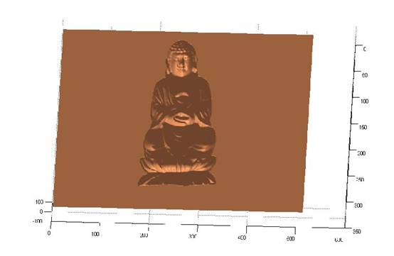
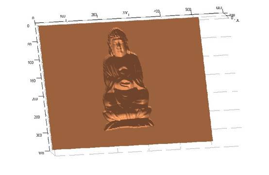
After computing the surface, use the surfl function to plot out the result of this project.
How to Run:
To run the program, the user would type the
following in the command line:
1. Open the sn_PhotometricStereo.m
file specify the image dataset you would like to use in the first line, it is ��dataset
= ��psimage/owl/owl��; by default; e.g. change ��owl/owl��
to ��cat/cat�� if you would like to use the cat dataset.
2. Then, save and run it. It would output the RGB encoded
image, albedo map and the reconstructed surface map
without albedo.
Experiment Data:
I have used four
datasets as experimental inputs. They are here.
Results:
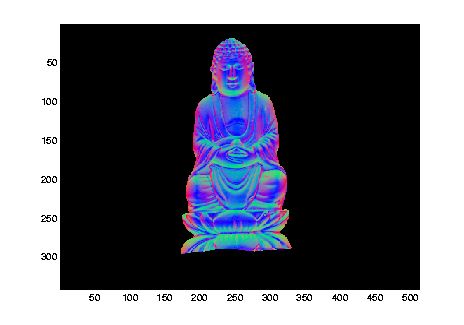
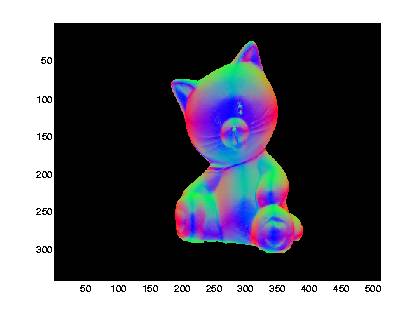
RGB-encoded normals:

albedo map:


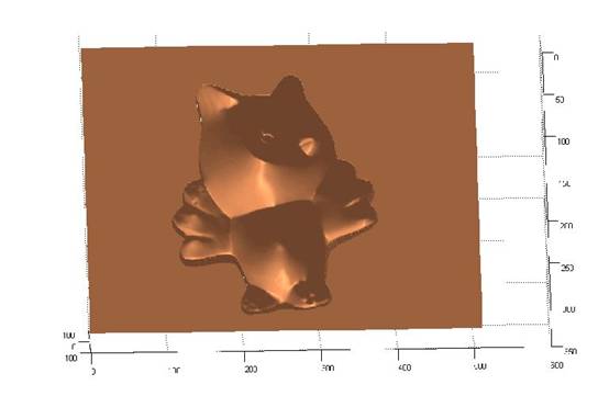
Views of the reconstructed surface without albedos:


Click here to take a
look at all the results.
Conclusion and discussion:
What worked and what didn't? Which reconstructions were
successful and which were not? What are some problems with this method and how to
improve it?
Result:
For most of the diffuse region it worked successfully, but for the regions
that is not completely diffuse and also those shadow (very dark) regions, it
didn��t work.
Improvement:
For those incompletely diffuse regions, reflection
components separation can be performed before reconstruction.
For reference:
Separation of Diffuse and Specular Reflection In Color Images Stephen Lin and Heung-Yeung
Shum.
http://research.microsoft.com/users/stevelin/pair.pdf
IEEE Conference on Computer Vision and Pattern
Recognition 2001 (oral paper)
For the shadow regions: remove the images contain the
shadows and use those without shadows.
References
1.
Woodham, Optical Engineering,
1980, Photometric
Stereo.
2.
Hayakawa, Journal of the Optical Society of America,
1994, Photometric
stereo under a light source with arbitrary motion.