CS 766 Project 2: Panoramic Mosaic Stitching
by: Adam Bechle
Introduction
The goal of this project was to develop a 360° panoramic image by combining many overlapping images. A camera was rotated fully about the scene to provide a series of overlapping images which covered the entire 360° viewing angle. The matching features in the overlapping images were used to compute the shift between each image. Then all of the images then shifted and blended together into one panoramic picture.
Image Aquisition
A Cannon Powershot A640 was used on manual aperture and exposure to take the pictures used in the panorama. The images were taken using a Kaiden panoramic tripod head, which rotated the camera about the camera’s optical center. This was done to ensure that all of the images were taken from the same point and only differed purely by rotation. Then, images were taken at intervals of 20° of rotation for a total of 18 images for the panorama.
Algorithm
- Radial distortion correction
- Cylidrical projection
- RANSAC feature matching/translation computation
- Image Blending
- Drift correction
- Image cropping
1) Radial distortion correction
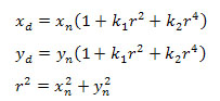
The images taken were subject to a barrel radial distortion due to the camera lens. The distortion of the lens is predicted with Equation 1, where (xn,yn) is theundistorted pixel location and (xd,yd) is the radial distorted pixel location.
 (1)
(1)
Since the images contained the distorted coordinates (xd,yd), an array of undistored coordinates (xn,yn) was created. The pixel intesities in the undistorted array were then interpolated fromthe distorted pixel locations to give an undistorted image.
2) Cylindrical projection
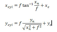
To give a smooth panoramic image, the images were projected onto a cylinder surrounding the camera with a radius equal to the focal length of the lens. This provides a better image stitching and blending than using a collection of flat images surrounding the camera. The coordinate transformation is computed with Equation 2.
 (2)
(2)
3) RANSAC feature matching/translation computation
To compute the translation between each image pair, the RANSAC method was used. The SIFT program was used to compute the matching points between each successive cylidrically projected image pair. RANSAC was used to find the best homography from 6 randomly selected matching points which included the most inliers. These inliers were then used to recompute the homography between the two images. From this homography, the average displacement of the matching inliers was found and used to translate the images.
4) Image Blending
The displacements computed with the RANSAC method were used to align the successive cylindrically projected image pairs. A simple feather weighting function was used to blend the two images together smoothly. This was done successively to grow the image to a full panorama.
5) Drift correction
Over the course of the image alignment and blending, the panorama drifted in the vertical direction such that the matching points on the opposite ends of the panorama were not aligned in the vertical direction. To correct for this, a simple linear global warp was applied to shift the image back into vertical alignment such that the opposite ends of the panorama were at the same vertical pixel locations.
6) Image cropping
The resulting panoramic image was cropped in the horizontal direction such that the ends of the panorama were continuous. This was done by using the same image as the first and last image in the panorama. The ends of the panorama was then cropped down the center of these individual images such that one half existed on each end of the panorama. The panorama was then cropped vertically to remove the voids left from the cylindrical projections.
Implementation
The algorithm was implemented in MATLAB using these scripts:
radial_cylindrical.m – Corrected the original images for radial lens distortion and then cylindrically projected them, saving the new files as “cyl_##.jpg’.
ransac.m – For each image pair, called the SIFT match function to compute the matching points and then implemented the RANSAC algorithm to compute and
save the translations between images. Calls the function homography.m to compute homographies.
homography.m – Function to compute the homography between two images.
blend_color.m – Alligned the images and blended them using the feather weighting function. Also performs drift correction and cropping.
Results
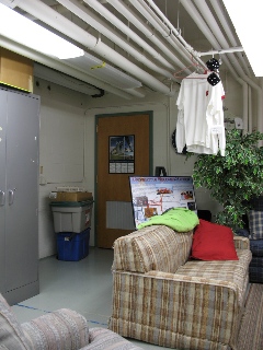
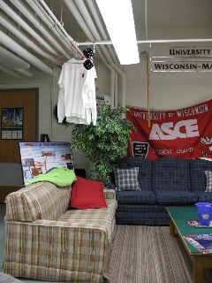
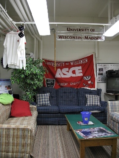
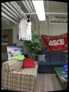
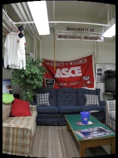
The Kaiden head and the camera were used to collect images at many location on the west side of campus, including Randall Park, the Engineering Centers Building, and Lot 17. Ultimately, the best panorama came from pictures in the American Society of Civil Engineers (ASCE) office. Three sample images are given in Figure 1, with their cylindrical projections in Figure 2. The full panorama is given in Figure 3. Additionally, there is a link to show the Live Picture panorama viewer. Overall, I think that the panorama looks pretty good and the seams are fairly unnoticeable to me. Hopefully, the web applet can be put on the organization’s website so we can show how awesome our office is.
|
|
|
Figure 1: Sample images from the ASCE office panorama |
|
|
|
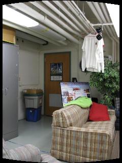
Figure 2: Cylidrical projections of images in Figure 1 |
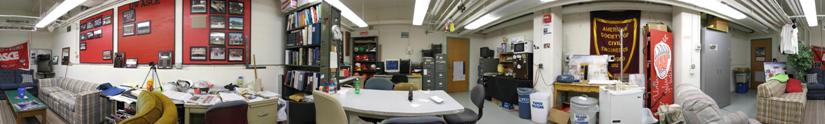 |
Figure 3 : Full panorama of the ASCE office
|
Live Picture view of panorama
Lessons Learned
The first problem I experienced was with the equipment. Many of my first image sequences were not of very good quality, as I could not get the rotations to lock, so there area images with very little overlap. After a few tries, I decided to rotate the camera based on the marked angles rather than locking in the head.
My first programming trouble came with the radial distortion correction. I took a while to figure out exactly how to use the equation to correct the image. At first, I actually distorted the image more than it was originally. My second major problem came in the RANSAC method. I neglected to ensure that exclusive points were being selected randomly, so my homography solution would be rank deficient, as I would use the same points multiple times to compute it. I finally realized this issue after reprogramming all of the equations in.
Also, I ran into difficulty programming when I attempted to stitch the images together. I mistakenly use the original image rather than the cylindrically projected image, so the alignments at the top and bottom of the image were not good, especially where text was featured on the seams. After wadding though the code to try to improve the alignment, I finally realized my mistake. In general, using the correct indices when creating the final image gave me quite a few problems and I probably should have thought about them a bit more than I did initially.
Reference Software
SIFT: Scale Invariant Feature Transform