|
CS/ECE 252 Introduction to Computer Engineering
Fall 2007 All Sections
Instructors
Mark D. Hill
and
Mikko Lipasti
TAs
Sanghamitra Roy,
Eric Hill,
Samuel Javner,
Natalie Enright Jerger, &
Guoliang Jin
|
Homework 4 Solutions
Problem 1
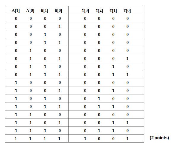
A 2-bit by 2-bit unsigned binary multiplier has two 2-bit inputs A and B, and 4-bit output Y. The 4-bit output is the product of A and B.
a. Draw the truth table for the multiplier.
b. Implement Y[3], Y[0] using AND, OR and NOT gates.

c. Given the blocks for implementation of Y[3], Y[2], Y[1], Y[0], construct a zero output checker, such that output ZERO is 1 if Y=0, 0 otherwise.

Problem 2
In a classic problem, a farmer, a fox, a chicken, and a sack of corn are on the left bank of a river. There is a small boat that will hold the farmer and at most one of the other three. Using as many trips as needed, the farmer must transfer the other three and himself to the right bank of the river. However, if he leaves the fox and chicken on one bank of the river while he is on the other bank, the fox will eat the chicken. Likewise, if he is on one bank and the chicken and corn are on the other bank, the chicken will eat the corn.
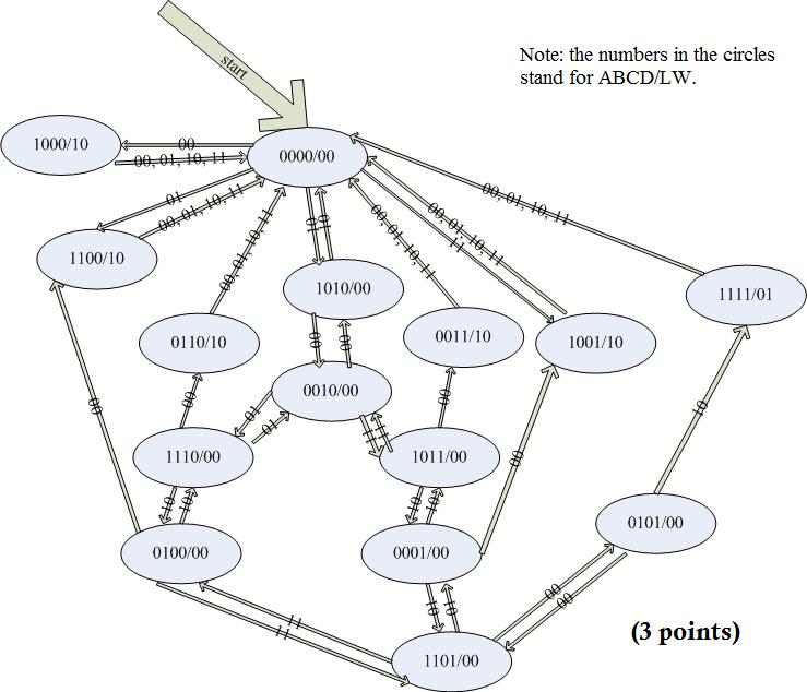
a. Draw the finite state machine diagram for this problem as in Figure 3.31 of ItCS. Each state value has four bits, A, B, C, and D, representing the farmer, fox, chicken, and corn, respectively. Each bit is 0 if its item is on the left bank and 1 if it is on the right bank. Two input bits, YZ, encode the action. If YZ = 00, the farmer crosses the river alone. For YZ = 01, 10, or 11, the farmer crosses the river with the fox, chicken, or corn, respectively. There are two outputs. Output L is set to 1 whenever the fox eats the chicken or the chicken eats the corn. Output W is set to 1 when all four reach the right bank of the river. Otherwise, no output is active. When either L =1 or W = 1, the machine resets to state 0000 on the next clock cycle.
b. Draw a block diagram of the sequential logic circuit implementation as in Figure 3.32 (a) in ItCS.

Problem 3
Problem 4.5 on page 111 of ItCS, omitting part b (3).
- Location 3: 0000 0000 0000 0000; location 6: 1111 1110 1101 0011(1 point)
- Location 0: 0001 1110 0100 0011 = 1 + 2 + 64 + 512 + 1024 + 2048 + 4096 = 7747
Location 1: 1111 0000 0010 0101 =
-(0000 1111 1101 1010 + 1) = -(4058 + 1) = -4059
(1 point.)
- 0000 0000 0110 0101 in ASCII is "e" (2 points.)
- skip
- Location 0: 0001 1110 0100 0011 = 7747
Location 1: 1111 0000 0010 0101 = 61477(1 point.)
- Add R7 R1 R3 or Add the contents of register 1 (R1) to the contents of register 3 (R3) and store the result back into register 7 (R7). (2 points.)
- The address points to location 6. Location 6 contains the binary value 1111 1110 1101 0011. (2 points.)
Problem 4
Problem 4.8 on page 112 of ItCS, assuming 256 opcodes and 127 registers (the numbers are changed).
- log2256 is 8. (2 points.)
- log2127 rounded up is 7. (2 points.)
- 32 - (8 + 7 + 7 + 7) = 3. (2 points.)
Problem 5
Problem 4.9 on page 112 of ItCS.
The other important operation performed during the FETCH phase is to increment the PC. (2 points.)
Problem 6
Please staple your homework together if it has more than one page.
Point awarded if your homework has only one page, otherwise they should be stapled together.(1 point)
|
