Introduction
Structured light illumination using phase shifting patterns is a widely used technique for 3D surface measurement. Even though it is robust to ambient light and object albedo, it may be susceptible to sensor and environment noise [Wang et al 2010]. The goal of this project is to obtain optimal structured light patterns which maximizes SNR and in turn increases the depth resolution.
Background
The method of finding a point in three dimensional space from its projections in many two dimensional images is called Triangulation. The diagram shown below shows the setup of triangulation.
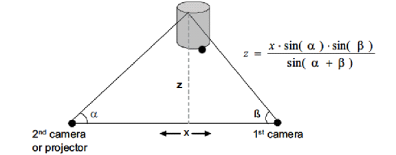
Passive triangulation involves the measurement of α and β which are the angles at which the object is observed from two different points A and B at a distance x. The perpendicular distance between the object and the base AB, z can be mathematically obtained using trigonometry. Stereo vision uses Passive triangulation. In active triangulation, a light source is used to project a point on the object and this point is inspected by a sensor which responds to changes in position. Instead of directly calculating angles like in the case of passive triangulation, the correspondence of the two triangles – object triangle and image triangle are the basis in active triangulation. Structured light is a method which employs active triangulation.
By projecting a familiar pattern onto the object of our study and then inspecting the distortion of the projected pattern, the object can be reconstructed. This method of reconstruction is called structured lighting. Using structured lighting fastens the measuring process as it displays a pattern of light onto the object using a pattern generator and its distorted reflection is captured by a camera.
To calculate the 3D coordinates of an object point, the image coordinates of the camera image and the number of coordinates must be known. In a simple scene, these can be obtained by counting in the camera image. For complicated scenes, a projected pattern is used. A few examples of patterns that can be used are binary codes like gray code , phase shifted codes etc. This project deals with choosing the optimal pattern that can be used to minimize the depth error.
Technical Part
- Derive a mathematical relationship between SNR and the length of the coding curve and observe that the length of the coding curve is proportional to the SNR.
- Mathematically analyze different patterns, their coding curves and lengths.
- Study different noise models and obtain an intuition on the various factors on which noise depends on.
- Based on that, develop a new pattern whose coding length is high and thereby higher SNR.
- Write an algorithm which computes mean error for a structured light system using a particliar type of pattern with a specific number of patterns. For example, sinusoidal pattern with 4 patterns; triangular wave pattern with 3 patterns. This can be used to compare mean errors computed for different type of patterns with a specific number of patterns. The main intuition behind computing this is that, as you increase the number of patterns even though the length of the coding curve increases, the SNR decreases. This error metric is expected to prove the above statement and it will also help in finding the reason behind the counterproductive nature of the length of the coding curve for higher lengths.
- Write an optimization algorithm which takes some of the existing patterns and the newly designed patterns, applies optimization methods to give an optimal new pattern.
- Write an algorithm for the implementation of a structured light system using the obtained optimal pattern and some of the existing patterns.
- Obtain results for various types of objects in practical scenarios and draw comparisons between different patterns.
Experiments carried out
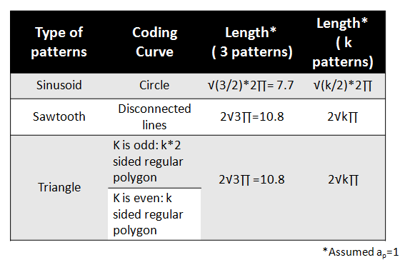
The dependancy between the length of the coding curve and the SNR of the curve was mathematically derived. Refer final report for the derivation. The following images show the lengths of coding curves of different patterns. Table 1 shows a list of patterns, their corresponding coding curves and their lengths when the amplitude of each pattern is equal to 1.
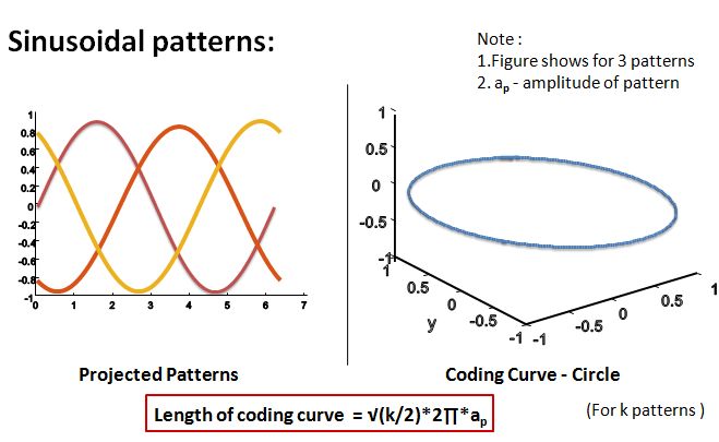
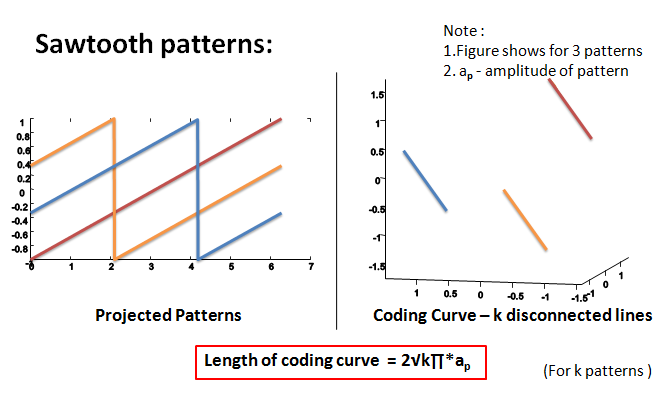
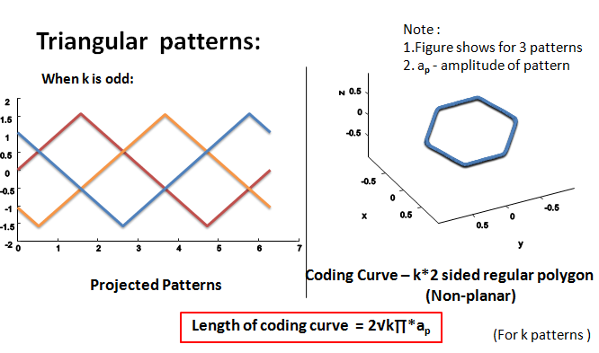
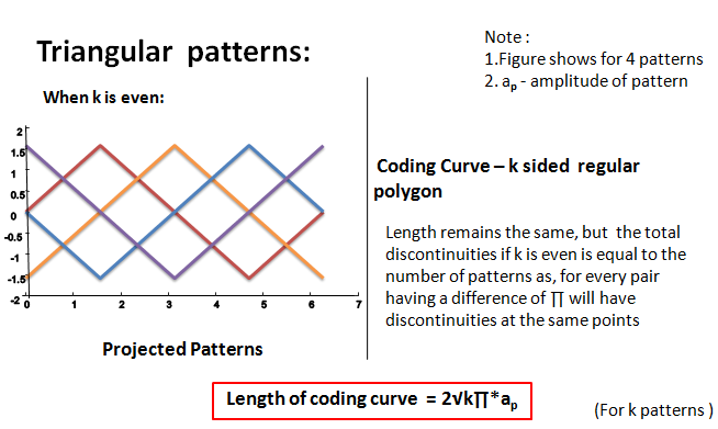
Table 1
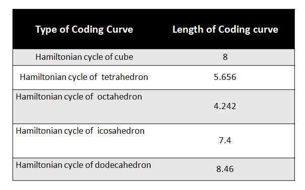
Hamiltonian cycle: It is a graph cycle in which each of the vertices is visited exactly once. Coding curves which are Hamiltonian cycles of n-dimensional shapes are used here. Table 2 shows a list of coding curves which have the form of Hamiltonian cycles of different shapes and their corresponding lengths. The lengths are high in the case of Hamiltonian cycle of a cube and Hamiltonian cycle of a dodecahedron.
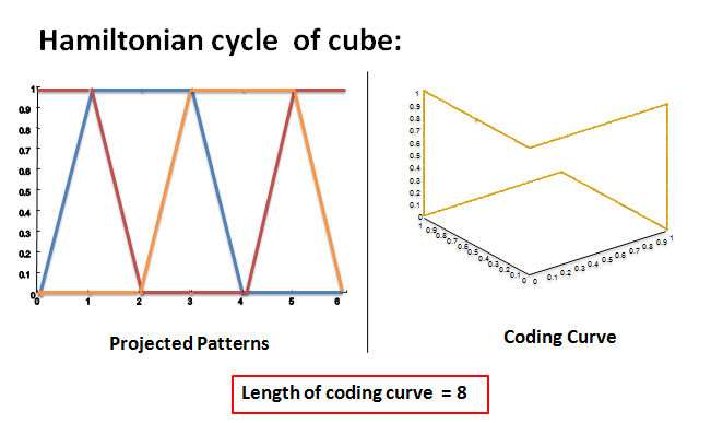
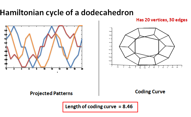
Table 2
Mean Error
An algorithm for computing the mean error while using a particular type of pattern with a specific number of patterns has been written.
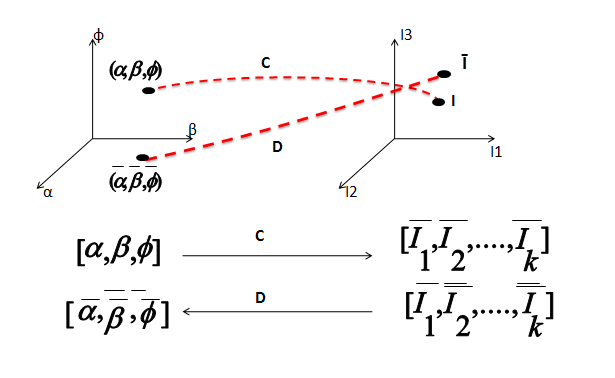
The above image shows the mapping of a pixel with intensities (I1,I2,I3) to the unknown space (α,β,φ) using mapping function D and the reverse mapping from the known space to the unknown space using mapping function C
The equation for computing the mean error for one particular (α,β,φ) is given by:
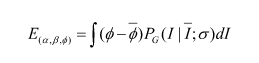
Where
α – Albedo value,
β – Ambient illumination,
φ- Depth value,
E (α,β,φ) - mean error over the entire intensity space for one particular (α,β,φ),
I – Intensity value,
Ī – Mean intensity value,
σ – Standard deviation for the intensity values,
PG – Probability of finding intensity value I with a mean Ī and standard deviation σ
in a Gaussian distribution.
The equation for computing mean error for all (α,β,φ) values is given by :
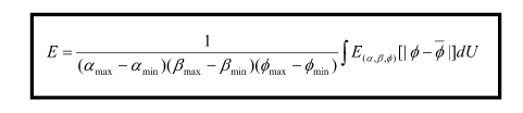
Where, U - unknown space ((α,β,φ) space).
Implementation of Structured light system
An algorithm for implementing the structured light system has been implemented with radiometric calibration. The algorithm includes implementation for projecting the below patterns and also decoding the obtained captured images to get the phase map. The phase map can then be triangulated to get the exact depth at that pixel.
- Sinusoidal phase shifted patterns,
- Triangular phase shifted patterns,
- Sawtooth phase shifted patterns,
- Patterns which get coding curve as Hamiltonian cycle of a cube,
- Patterns which get coding curve as Hamiltonian cycle of a dodecahedron.
Conclusion
Compared to the conventional phase shifting methods, the new optimal pattern is expected to give a higher depth resolution. This result will alleviate the huge distortions obtained in the depth measurements caused by sensor and environmental noise. The comparison table will be an easy look-up table to decide what kind of patterns to use, number of patterns to use and the tradeoffs that have to be made.
Future progress of the project is to formulate the optimization problem which takes different patterns as the input variable and minimizes the mean error.