The objective of this problem is to design a 4-bit comparator hierarchically. You are allowed to use only inverters and 2-input NAND gates.
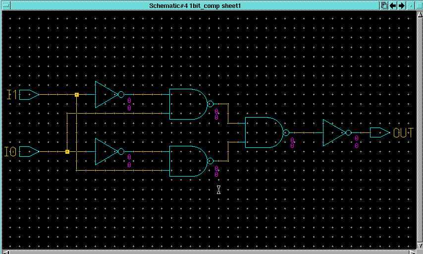
a) Design a 1-bit comparator using only inverters and 2-input NAND gates. This comparator has 2 1-bit inputs. Its output is 1 if and only if both
inputs are the same. Implement
the circuit in Mentor Design Architect. Create a symbol for the 1-bit
comparator. NOTE: The input data lines of the comparator should be labeled starting with
I(1:0) (eg I1, I0) and the output with OUT.

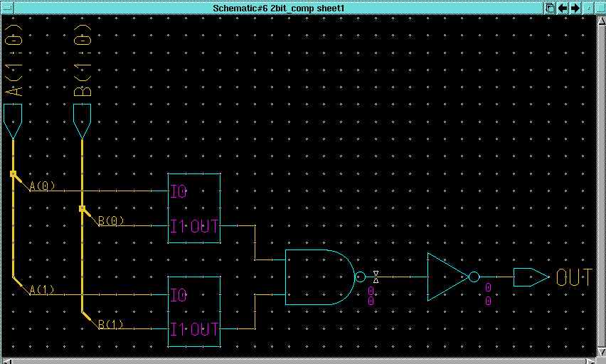
b) Use the symbol of the 1-bit comparator you designed in part (a) to hierarchically create a 2-bit comparator. Create a symbol for your 2-bit comparator.
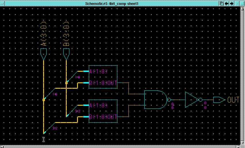
c) Hierarchically create a 4-bit comparator using the symbolic version of your 2-bit comparator.
The inputs to the new comparator should be 4-bit buses (NOT single wires) labeled "A(3:0)" and "B(3:0)",
and the output should be a single wire labeled "OUT".
Test the comparator you created using QuickSim II and print out annotated results
of your simulations.
a) Design a 3-to-8 decoder, again using only basic 2-input gates. Implement the circuit in the Mentor Design Architect. The circuit should have inputs labeled I2 through I 0 and outputs labeled OUT7 through OUT0. Create a symbol for your decoder.

The objective of this problem is to design an 8-to-1 multiplexor (mux) hierarchically.
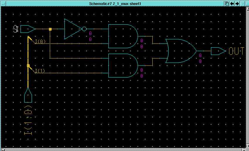
a) Design a 2-to-1 mux using AND, OR and NOT gates. Implement
the circuit in Mentor Design Architect. Create a symbol for the 2-to-1 mux.
NOTE: The input data lines of the mux should be labeled starting with
I(1:0), the select line should be S and the output line with OUT.
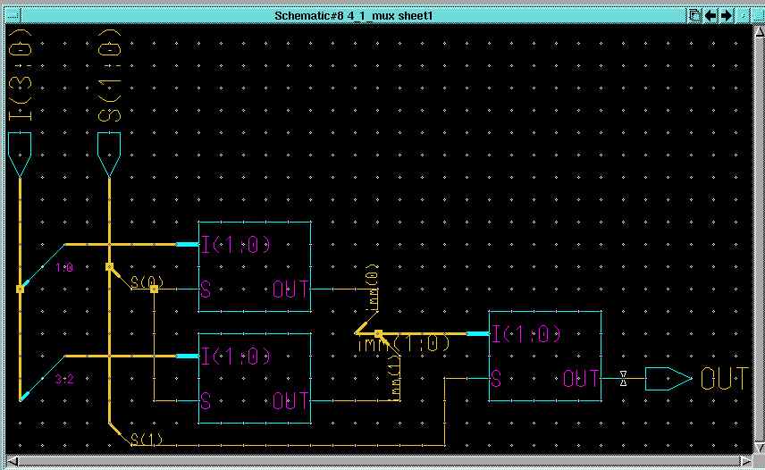
b) Use the symbol of the 2-to-1 mux you designed in part (a) to hierarchically create a 4-to-1 mux. Create a symbol for your 4-to-1 mux. NOTE: Make your select-bus (not single wires) S(1:0) i.e. S1 and S0
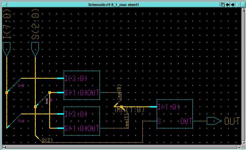
c) Hierarchically create an 8-to-1 mux using the symbolic version of your 4-to-1 mux.
The inputs to the new mux should be 8-bit bus (NOT single wires) labeled "I(7:0)" , the select-bus labeled S(2:0)
and the output should be a single wire labeled "OUT".
 Problem 4; 35 points
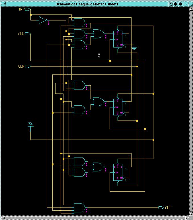
Design a sequence detector that detects the sequence that corresponds to the last two digits of your student ID, represented in binary coded decimal. For example, if the last two digits of you student id are 1234567890, the sequence detector will detect 90, which is 10010000 in BCD.
You should complete each of the following:
Say, the last two digits of your ID are 10 (decimal) . The corresponding
BCD code is 00010000. The following state diagram is of a machine that detects
this input sequence.

This is a Mealy model , in which the output is a function of both state and input, therefore the output
goes high as soon as the last bit in the sequence is read. You can also use the Moore model, in which the
output is a function of only the present state. In the Moore model, the output is delayed
by a clock cycle.
