A local ham has a Flex-5000 SDR that stopped working. As I understand it went back to the manufacturer and was deemed unrepairable. I don't think he was OK with that answer and I was also suspicious -- he asked if I'd be willing to take a look.
The symptoms this radio presented were that it would take power, turn on, light the front LED for 3-10 seconds and then power off. Weird!
The Flex-5000 schematics and bill of materials are available from the manufacturer which greatly helps debugging. I was familar with the Flex-3000 and SDR-1000 hardware which helps for generally not having to wonder if my own PowerSDR or firewire interfaces were suspect.
Step one -- download schematics, determine initial conditions, visual inspection. Is everything plugged in? Anything burnt? Cracked? Is it plugged in? All looked good here. Power up the unit, press the power button, all looks good for maybe 5-15 seconds. Unit goes dead.
Next -- verify voltages. There are quite a few regulators for each subsystem in this radio, check that all are OK. They were.
The main CPU has a serial port -- two of them actually -- that present data. In the Flex-5000 the main and second serial port are at RS232 levels. Output on the serial port existed and didn't show any missing subsystems. Not dead, that's for sure!
The Flex-3000 and Flex-5000 use I2C to communicate with all of the sub circuit assemblies on the radio. I connected my Saleae logic analyzer to the I2C bus and configured the I2C analyzer. From here I mapped all of the called I2C addresses to chips on the schematic and looked for patterns in the output. One of the multiplexer chips actually *can* turn off the radio. Does it?
Output from the logic analyzer terminal
After a long time looking at datasheets I concluded -- the radio isn't turning itself off. It seems fine.
Could it be something in the logic circuitry that powers up the radio? There are some FETs and a flip flop. Maybe? As I test I held down one of the lines that causes the FET to supply power to the radio. Weird, it still turns off!
In the process of testing the power logic circuitry I noticed the LM7805 regulator on the PO board was getting hot. It's normal for a linear regulator to run warm, but this was HOT. Further inspection showed that the linear regulator was not secured tightly to the underlying heatsink. It overheated and the radio shut down. Two turns of a screwdriver and all's good.
In retrospect I could have used my thermal camera to determine the problem with this device more quickly. I did use the thermal camera on the HRF board (uninteresting) but I see I did NOT inspect the PA board.
Lessons learned/reinforced: it's probably still power. Major problems are still probably simple. Continue to check the boards with the thermal camera, but inspect ALL boards as everything is interconnected. In this case, what appeared to be a complex logic failure on one board was a simple mechanical issue on a different board.
June 2020
Radio returned with inconsistent power.
I wasn't able to duplicate the inconsistent power but took a look at PA board temperatures to rule out overheating. I took out the tuner, replaced it with a jumper for a full view of the PA board. From there I sent long CW dashes at full power into a load and watched for changes.
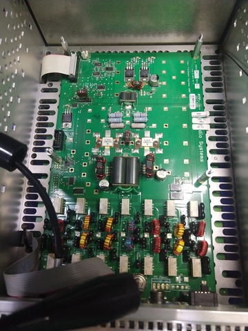
PA board in 5000
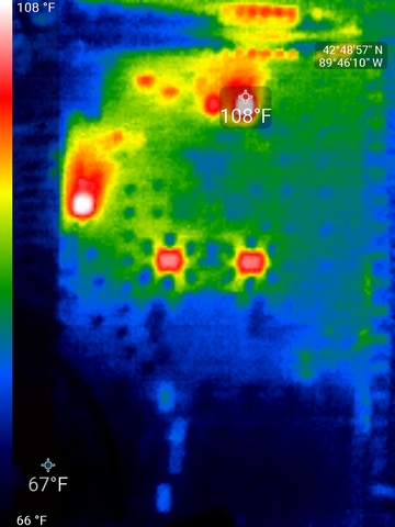
IR image at start
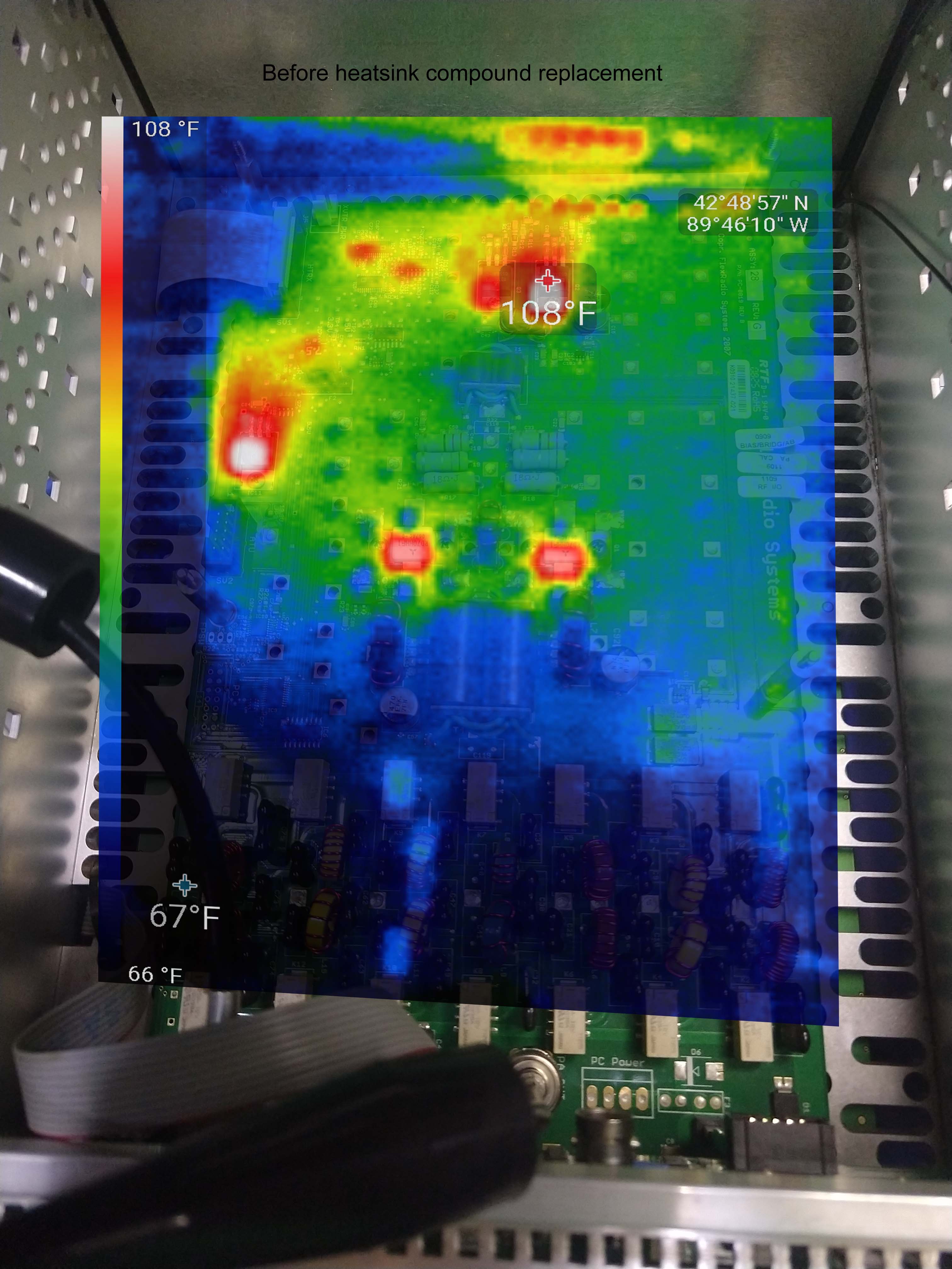
"before" IR image overlaid on PA board
See also:
In the 'before' and in the video you can see that +5V regulator on the left and interestingly the two drivers getting quite hot, unequally so -- much hotter than the final amplifier transistors. I would not expect the drivers to be hotter than the final amplifier transistors.
So I removed the board.
What I found was the old heatsink compound appeared to be painted on the devices but exceedingly little residue was left on the heatsinks to which they were mounted. A dab of compound is all that's needed -- but I didn't expect to see none on the heatsink as every heatsink compound I've seen tends more towards getting everywhere than not.
So I started over and cleaned it all off with isopropyl and a chem-wipe for good measure. I razor-bladed on a thin layer of GC type Z9 heatsink compound and reinstalled the board. (GC Z9 isn't anything special, it's just a good silicone heatsink compound.)
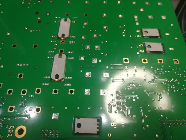
Original heatsink compound
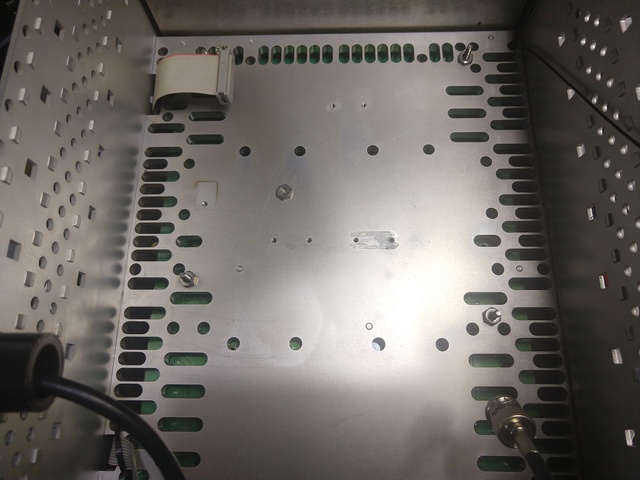
...very little trace of original heatsink compound on board.
Afterwards -- note 'after-heatsink.jpg' and 'IR-after.jpg' -- the regulator is cooler, the drivers are significantly cooler and the PA transistors are only around 100F.
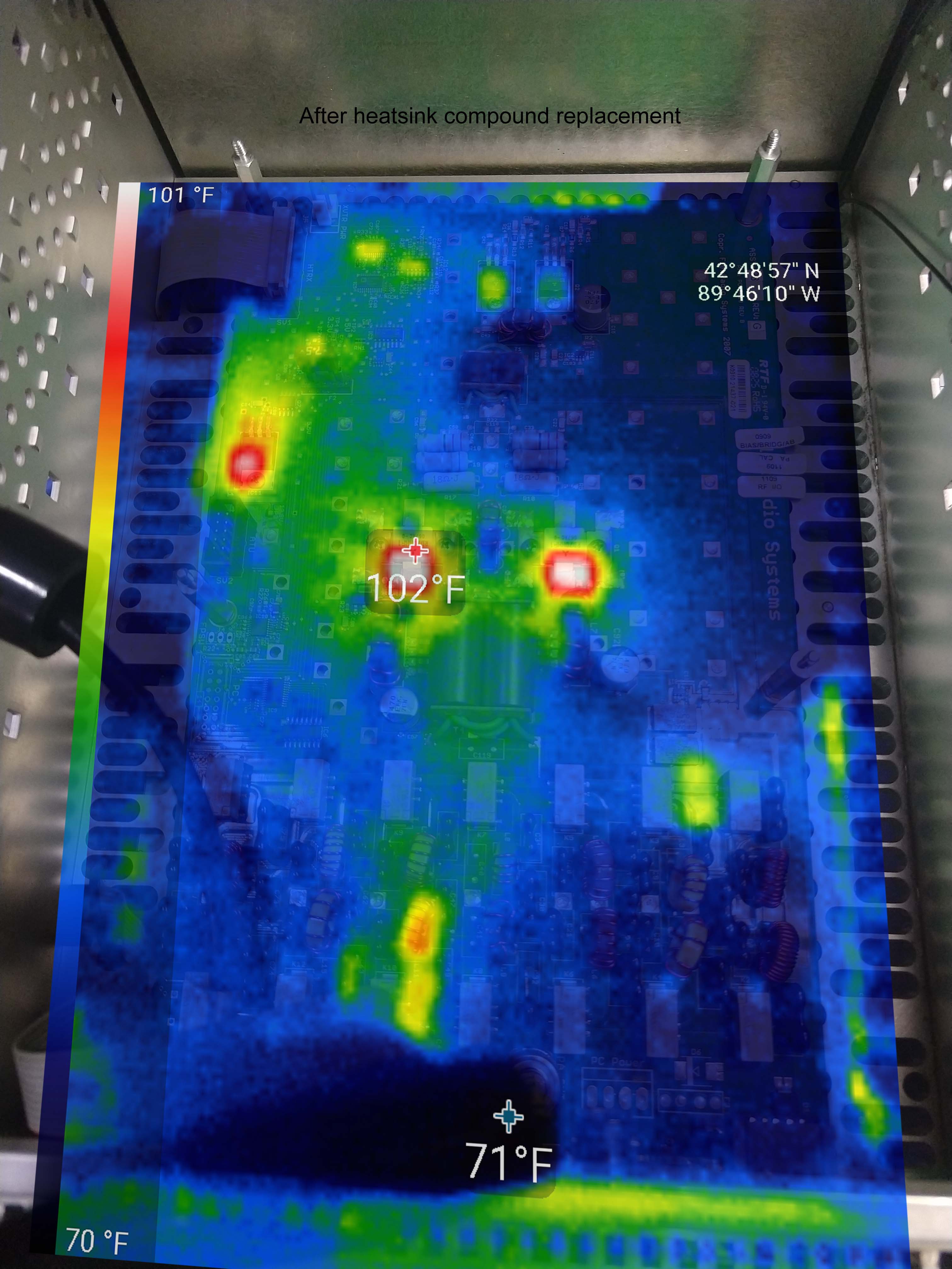
After composite of replacing heatsink compound. Note the drivers barely show and the finals are not as hot.
So I don't know if this is a solution to the but I think it's a net improvement in operation. I havent' seen any drp in power on TX, the wattmetre parks itself on a little over 100W during TX in testing.
In any case, I've seen no power drop on TX -- the Bird parks itself at the same maximum during TX or on peaks during testing.
26 June 2021
While running FT8 at 40W on 6M into a non-resonant antenna via the internal tuner I heard a pop and smelled something -- immediately I shutdown and checked things out. No power out through the tuner but OK in bypass.
The internal tuner on this Flex-5000 is the older model, a LDG AT-200 PC, it looks like Flex eventually designed their own based almost completely on the AT-200PC design -- a point which is important shortly.
I never found any signs of problems on the board such as smoke or a cracked toroid or capacitor so I opted to remove ALL of the relays and test. Prior to that, I did order replacements from DigiKey for approximately $3 each. $40 was cheaper than the labor to do this again or wonder if I really found all of the bad relays.
One relay had about 200 ohms resistance in the NC position. That would do it. Before replacing all relays I made a hand-drawn schematic. I also measured all of the inductances and capacitances with my LCR meter. All seemed reasonable.
This is an L-network tuner with a relay (K16) on the output to switch between antenna output #1 and #2 -- in the original LDG configuration, not used in the Flex.
The tuner was replaced and it still did the same thing -- tried to tune but no power out in the meantime. I did some further testing. Connecting the radio PA output to a wattmeter shows it was making the indicated power (10W) while trying to tune. When the tuner was disconnected (effectively in bypass) power out was fine. I removed the tuner again. I was able to connect the tuner on the bench to a PC with software: https://github.com/csylvain/LDG-AT-200PC-Control-Program and control all relays independently as I stepped through all C and L combinations. Using my LCR meter I was able to measure reasonable values while stepping through individual L and C values.
Back in the radio but with external software control. In this configuration all works as expected -- the tuner works flawlessly. But not under Flex control. In the meantime I found a schematic of the updated Flex tuner. It was the SAME as the LDG unit down to part numbers but it had TWO relays to bypass the inductance chain and didn't have the unnecessary output.
What I found was K16 on my unit selected the second antenna output. K16 is a bypass relay on the flex tuner. During tune, K16 was energized (there is no K17) to put the L network "inline" but on my unit selected the second output which connected to nothing.
My solution was to solder some braid on the bottom of the board of K16 to always enable the primary output without regard to state of K16. Fixed.
Tuner firmware as reported by the PowerSDR console is the most up-to-date, but I think this may be inappropriate for the older tuner. I could not find firmware or release notes or a method to downgrade firmware so I think the jumper stays. It may have been cleaner to pull the relay and use a wire jumper but this works and is easy to reverse.
This page last modified Sun Jun 27 11:24:06 CDT 2021 by timc!