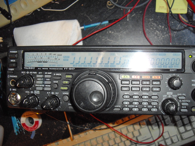
The Yaesu FT-847 is a HF/VHF/UHF all-mode transceiver with DSP that is capable of full-duplex operation for satellite use. I found one for sale on ebay -- not working -- it was in a house fire but was not the item on fire. The price was commensurate with the challenge and risk I was willing to accept.
The previous owner did a fair amount of cleanup on the radio. In fact, it was much cleaner than almost every other radio I've purchased off ebay, but still had some lingering soot issues.
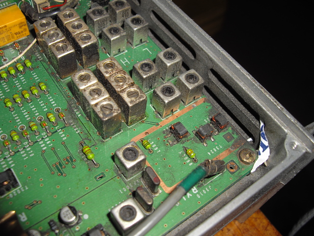
RF/BPF board, note the black soot and shredded paper shipping detritus
First thing I had to do was clean the radio. The front panel, skins, and knobs were all removed and scrubbed with a toothbrush and some "Mr. Clean" spray cleaner and then rinsed with clear water a few times and left to dry.
A complete disassembly was necessary to clean the boards. The radio consists of seven separate circuit boards interconnected via wire harnesses and coax cables. It took several hours to pull each connector and label the connector from which it was removed. There are 60-70 connectors in total. Once free, each circuit board was removed from the chassis and static bagged.
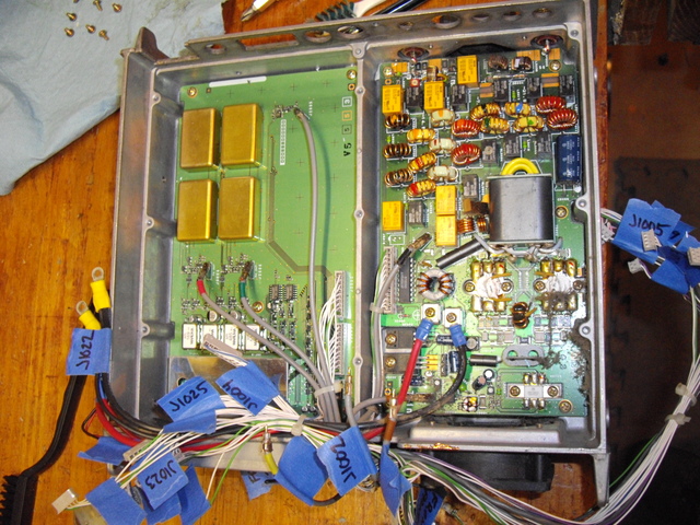
Partially disassembled, note the blue tape (my favorite!) with the
location for each connector
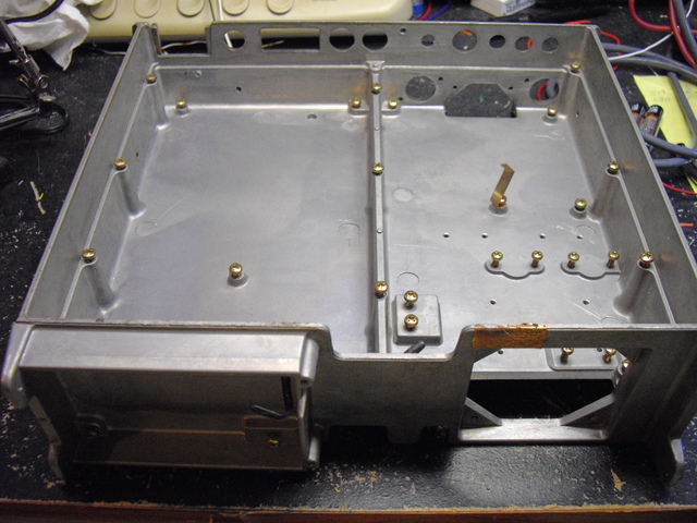
The bare aluminum chassis was also scrubbed with IPA and "Mr. Clean". I opted to discard all but the connectors from the cooling fans and purchase new from DigiKey. The radio may have been ON (and circulating smoke) during the incident. I can't tell. The fans weren't worth cleaning.
The following are the replacement fans I ordered:
small fan: DigiKey 563-1139-ND
large fan: DigiKey P14740-ND
Both fans exceed the specs (CFM) of the original fan and have lower
noise ratings. You'll have to solder the connector on these fans, but
they fit exactly.
It's almost certain that Yaesu Parts would have had these in stock too. In fact, most of the FT-847 parts (think switches, knobs) I'm seeing on ebay are 10x the cost of ordering them directly from Yaesu.
After removal, each board was individually sprayed with isopropyl alcohol (IPA) and gently scrubbed with a soft toothbrush several times. When they were "clean" I did a final rinse and dry with more IPA.
Reassembly is uninteresting -- put everything back where it came from. The wire bundles were all separated and each strand cleaned with a paper towel and more IPA. Interestingly the smell from a fire was undetectable at this point, significantly different from a cigarette-smoke radio -- which is damn near impossible to clean to a state where it doesn't smell. Soot was almost completely removed, there's still a little I can't get off the chassis but it's not going to rub off either, so whatever.
The radio didn't power up on first try. I found a tiny void in the trace leading to the front panel switch -- not the usual FT847 power switch failure. I patched that under my 10x stereo microscope, bridged the switch to stave off future failure and was able to successfully power the radio.
Unfortunately the display was garbled. Poking around with the oscilloscope, there was no data flowing between the head and cpu. The display cpu had voltage but not oscillation on the crystal oscillator. A reset didn't do anything. The crystal appeared to oscillate at/near the desired frequency when tested.
I was able to acquire a new front panel on ebay (minus the display) which appears to work fine.
Now that I can tune the radio...there appears to be no receive on any band. Just static.
The Yaesu FT847 service manual is no longer available from Yaesu parts and the copies on the internet vary from incomplete to unreadable.
Fri May 23 22:02:00 CDT 2014
Testing what I could, the output from the PLL board was non-existant. The PLL voltages were basically sawtoothing up back down at a rapid rate. Again, another PLL board was sourced from ebay. Thankfully, success upon installing the board. The radio now receives on HF, 2 and 70cm. Just how well is a good question, but I can work on that.
Irritatingly, the CW mode doesn't work. When you hit the CW button the radio goes into transmit which causes my current limited supply to shut down and on and on.
Additionally a previous owner modified the radio to transmit everywhere. I changed it back to the factory config.
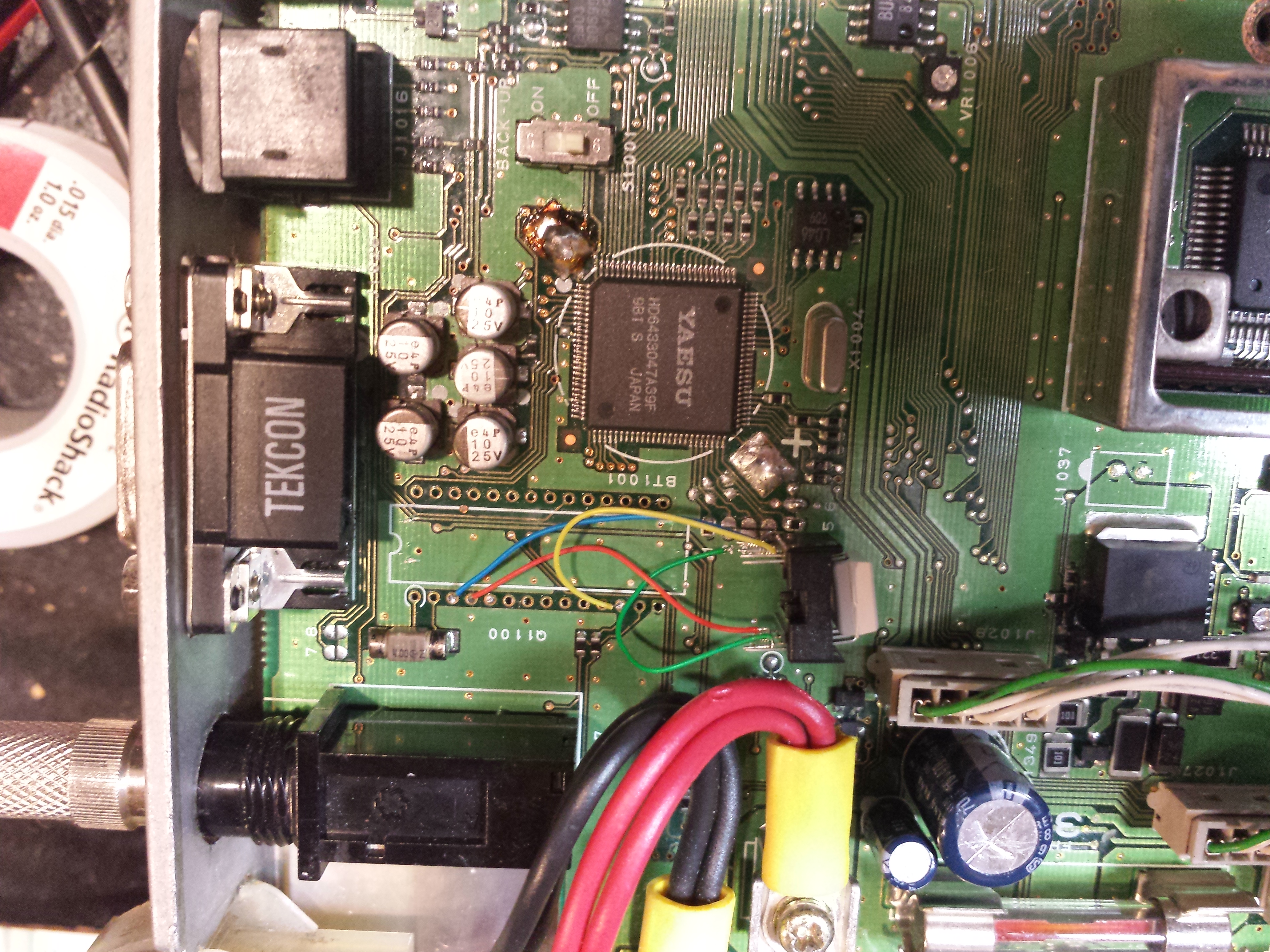
Now that the radio won't TX out of band, I could place the radio out of band and go into CW mode. The message "Error" flickers on the display. It appears as if the keyer chip (Q1100, a MB8854, one-time mask programmed thing) is stuck in TX...no matter what. Pin #4 is the output to the radio and the oscilloscope showed a ~10kHz (!) square wave there.
I desoldered the keyer chip. The radio now goes into CW mode just fine and shorting pin #4 to the CPU causes the radio to TX a tone. I'll probably replace this chip with an opto-isolator for the time being. I see that the Yaesu FT-890 and FT-990 both use the same keyer chip, so theoretically I could repair it. Somehow the CPU also communicates with the keyer chip via three lines to set it for straight key or iambic mode. I couldn't see any activity on those lines so I'm not sure what's going on. If I could, it would be a relatively simple matter to program a replacement PIC or AVR to handle keying as per the original methods. It will be low on the priority list as I'm using an external keyer anyway and really don't want to live without the CW memory functions that aren't in this radio anyway.
Next up, test the power out, sensitivity and verify alignment.
Sun May 25 17:20:25 CDT 2014
Not a scientific test, but it's CW WPX weekend. Tuning around with my IC706 the bands are busy. I put the antenna on the Yaesu -- the bands seem equally busy.
I probably would have checked power out if my high-current DC cable was longer than 24 inches.
Remaining issues:
CAT doesn't work -- MAX232 converter deadI want to change the serial port to an on-panel USB jack...I think I need the CC-USB232
CW keying circuitget a power cable- power output checks
- verify alignment
The FT-847 also has some modifications that others have come up with over time -- since I'm elbows-deep, why not:
- AF gain fix -- make bottom 30% work
- diode replacement -- but more reading makes me think this may be a gimmick
- fix the PLL board
- ensure front panel mic muted when using data connection on back
- get a microphone?
Sat May 31 23:05:28 CDT 2014
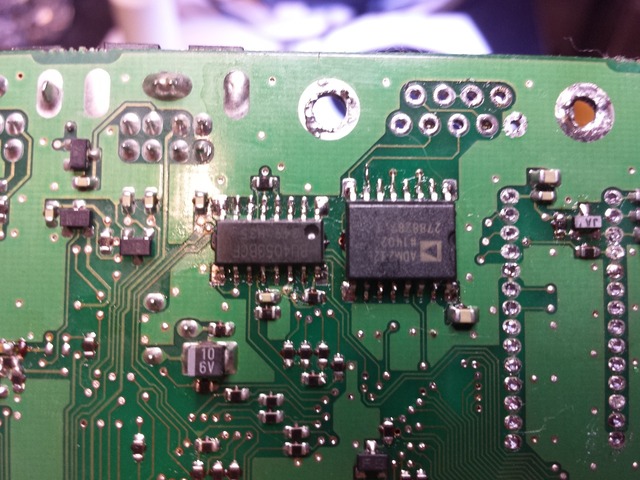
ADM232LJR (TTL-RS232 convert) and BU4053BCF MUX (to switch CPU serial port between the serial port and the tuner port) both replaced. For the cost of acquisition, I'll just replace both. CAT on the FT847 is now working again.
USB adapter ordered!
Tue Jun 3 22:56:56 CDT 2014
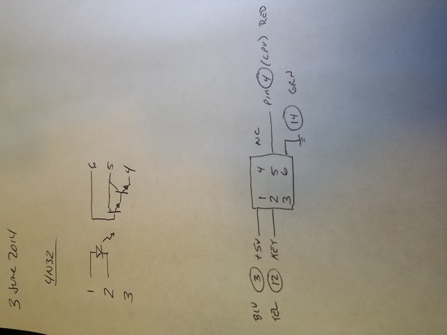
Keying circuit installed. I used a 4N32 to isolate the external key from the CPU. This seems to work just fine.
6-pin DC cable also arrived. Connected to my 20A power supply and I don't get any power out from the radio. When I either key with CW or just enter MOX, the fans ramp up and DC current goes to about 5A. No power out -- in fact, I can't even hear myself in a nearby receiver. This was tested on both 14 and 50MHz. HF and VHF receive sounds great. (Nothing on 70cm nearby that I would expect to be able to hear.) The fact that it's uniformly affecting both HF, 6 and VHF (probably UHF too) makes me think the problem is further up/back.
Further keyer investigation: When the 'keyer' function is activated, pin 20 has a 128mVpp, 146hKz signal. Goes away when the keyer function is disabled.
When key 'keyer' is off, pin 18 has a 46mVpp, 146kHz signal.
Still no good ideas for what's going on with keyer weighting on pins 24, 25, 26, 27.
According to the FT990 service manual:
| ratio | 1 | 2 | 3 | 4 |
| 1:3.0 | O | O | O | O |
| 1:3.1 | X | O | O | O |
| 1:3.2 | O | X | O | O |
| 1:3.3 | X | X | O | O |
| 1:3.4 | O | O | X | O |
| 1:3.5 | X | O | X | O |
| 1:3.6 | O | X | X | O |
| 1:3.7 | X | X | X | O |
| 1:3.8 | O | O | O | X |
| 1:3.9 | X | O | O | X |
| 1:4.0 | O | X | O | X |
| 1:4.1 | X | X | O | X |
| 1:4.2 | O | O | X | O |
| 1:4.3 | X | O | X | X |
| 1:4.4 | O | X | X | X |
| 1:4.5 | X | X | X | X |
Wed Jun 4 23:15:09 CDT 2014
More debugging. Radio doesn't transmit. TX LO from PLL board ok. TX IF from AF/CTL -- nothing. Followed back to the 1st and 2nd mixer, no signals. Back to TX DDS -- no signal out. Crap. However, the 6.73 MHz signal in -- it gets to the RX DDS but not to the TX DDS.
Probing Q1125...the 6.73MHz signal gets there but not out. But where's the bias/power on the transistor? Fortunately there's another exact DDS unit on the board where I can compare voltages -- in fact, there's no +5V to the DDS at all. Probing further, it looks like L1013, a 330uH SMD inductor is not passing any DC.

inductor -- failed open
Upon removal, the inductor is definitely a DC open. I don't have any 330uH SMD inductors, but I do have a 120uH. I don't think the value is critical for late-nite (wait, it's 12:20 a.m.?) go/no-go testing -- it's DC filtering. I install what I've got.
It transmits!
I don't know how much power out, but it's enough to make my auto-tuner do its thing, which is more power out than before. I'll get my wattmeter connected later.
I'll order a replacement inductor with the correct value from DigiKey later; this will do for now.
update: 330uH inductor replaced 22may2020 -- six years later...
Mon Jun 9 23:09:52 CDT 2014
The CC-USB232 arrived.
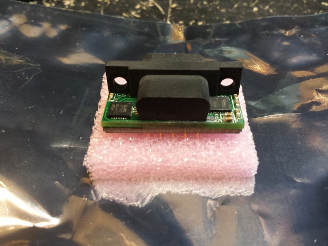
The CC-USB232 is a drop-in replacement for the Amphenol board-mounted RS232 connector used on many devices including the FT847. It's a a drop-in replacement, almost.
The FT847 is wired DTE, just like a PC serial port. That's why everyone needs to use a null-modem cable with their '847. The CC-USB232 is wired DCE (which makes sense!), so I need to swap lines 2 and 3 on the Yaesu. The other flow-control lines are looped back on the radio, they can be ignored.
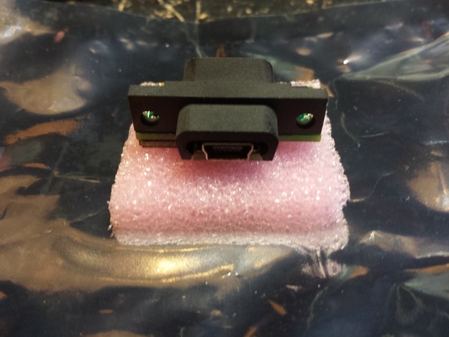
Some closer pics of the device. They really did a nice job of shoehorning this functionality within the space defined by someone else.
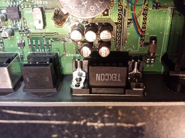 The original RS232 connector.
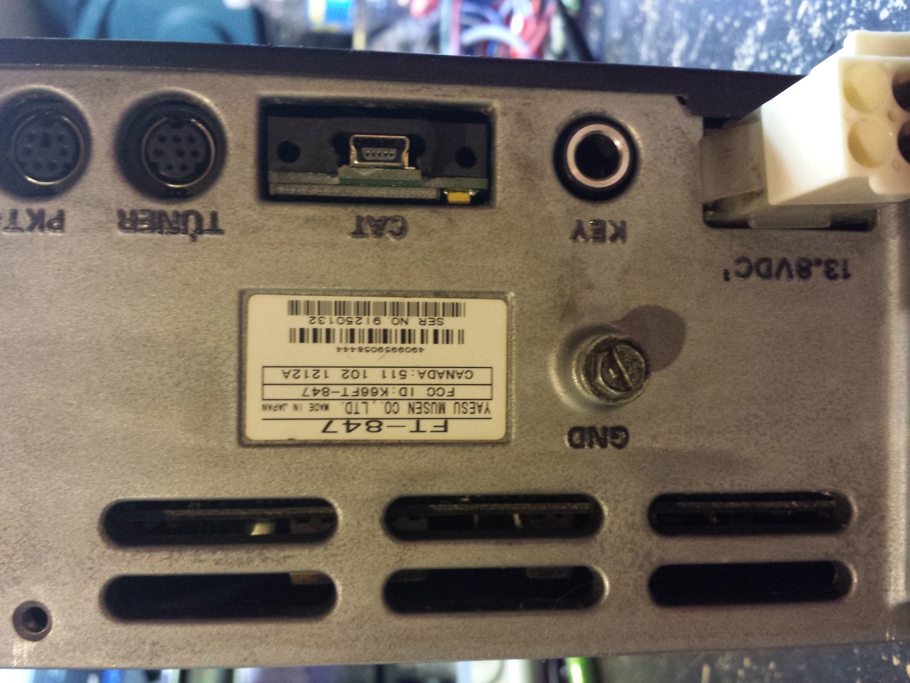
 Ever notice pads 7 and 8 on the radio back by the RS232 connector?
Pad 7 connects to pin 4 (DTR) on the RS232 port.
Pad 8 connects to pin 8 (CTS) on the RS232 port.
The common set of pads connect to pin 1 (DCD).
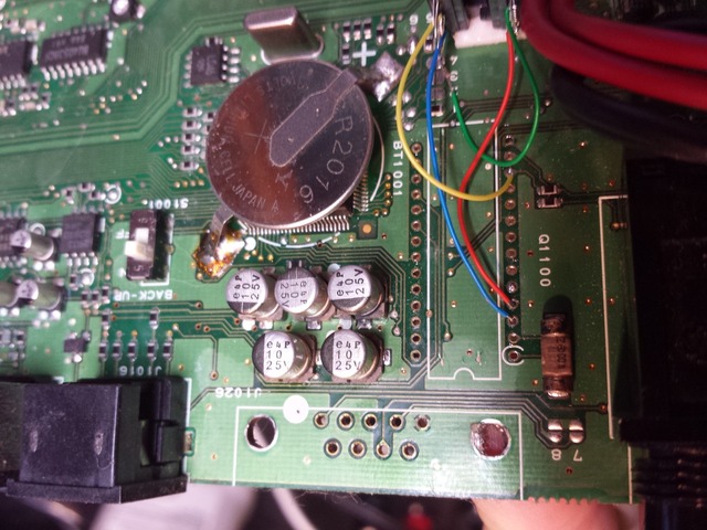
 This is the original wiring from the serial port to the RS232 level converter.
Pins 2 and 3 will need to be swapped.
This is the original wiring from the serial port to the RS232 level converter.
Pins 2 and 3 will need to be swapped.
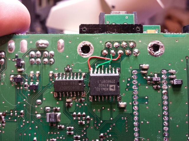 I cut the traces and tacked in a couple of wire-wrap wires. If I ever need to
change back, it's easy.
I cut the traces and tacked in a couple of wire-wrap wires. If I ever need to
change back, it's easy.
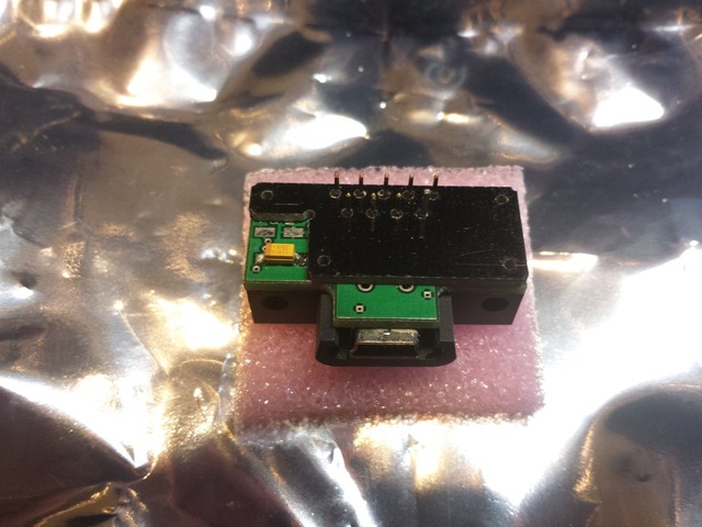
 The back panel of the radio with the mini-USB connector.
Sun Aug 3 20:43:10 CDT 2014
Not much of an update -- have been too busy using the radio! Mostly the W1AW portable stations and a few 6M contacts. I now have a box to connect my aviation headset to the mic/phone jacks and next up is connecting the USB232 RTS port to the data jack to actuate PTT for data modes.
Sun Aug 3 21:59:10 CDT 2014
Aviation headset connection information
I found a David Clark H10-30 aviation headset (along with a couple older Sigtronics headsets...) at the Madison hamfest a few years back -- for a great price. Of course I bought them! I updated the headset with new gel earseals and a new sock for the mic. To date, I've mostly used it for receive -- it does a great job of blocking out external sound and audio quality for voice is great.
The microphone on this headset is a M-1/DC dynamic microphone. Various sources on the internet, including specifications on the David Clark website produced the following info:
- 8-16VDC bias, not polarity sensitive
- 220-2200 ohm impedance
- 40mV output at 150 ohm impedance
The Yaesu FT847 has 5V available on the 8-pin mic jack. The Yaesu manual claims 200-10K ohm impedance for the microphone.
So...close enough to try out. Using a metal project box (that I don't quite care for) I installed an RJ45 jack for mic audio and an 1/8" jack for earphone audio. An 18" cable converts the 8-pin mic connector to RJ45 and allows for future use with other radios. Also on the box is a 1/4" tip-ring-sleeve jack for the headphone audio and Switchcraft S12-B jack for the microphone. The mic plug on aviation headsets is a little smaller than 1/4" -- 0.210" -- the Switchcraft S12-B jack is the correct size for this application.
A couple of buttons for PTT, up and down round out the box.
Wiring. You can find a lot of information on-line for how to do this, but I went by this which seemed straightfoward enough.
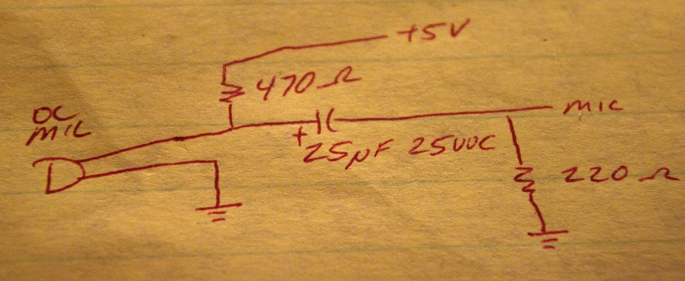
So yeah, wire that up. Using the monitor function on the radio I can tell around 50% drive is the max before distortion sets in. A very level voice (i.e. don't get excited) sounds OK without additional adjustment.
I tack-soldered an audio transformer in circuit to see if it made difference, one of the common Radio Shuck 1K to 8 ohm things. It did reduce the level into the radio a bit but I can't say it made things better so I took it out of the circuit for simplicity.
So...it works. I've only made 10 or so contacts so far -- which is a lot for home actually -- nobody has said anything about my audio quality -- so I guess I'll go with it.
IF panadapter tap
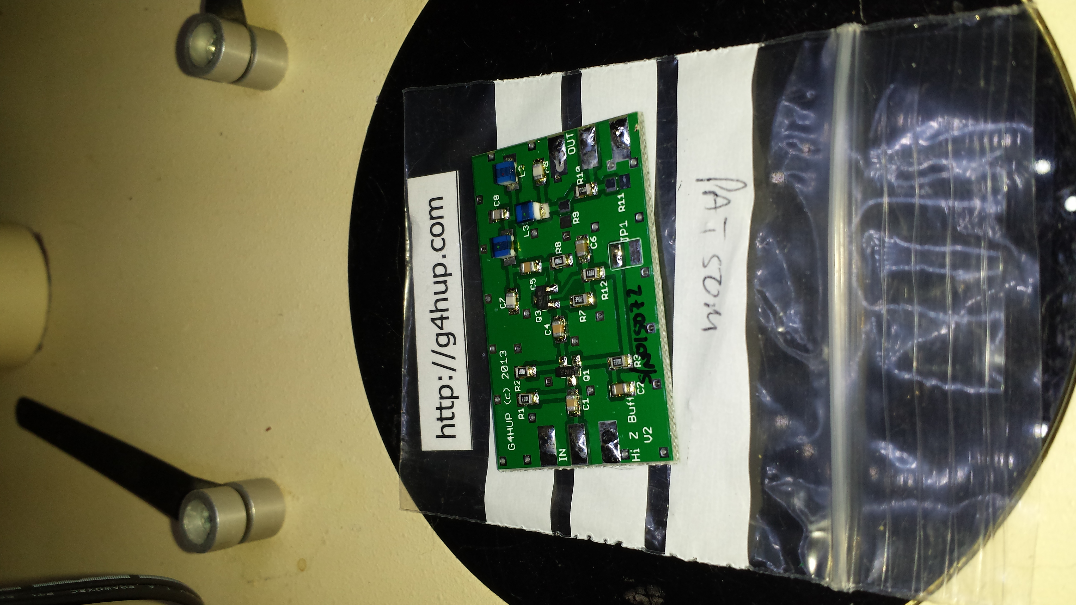
The first step is a buffer amplifier for the IF -- I purchased mine from G4HUP -- mine shipped from the US fully assembled and together with his excellent rig-specific documentation I was able to easily integrate it with my FT847.
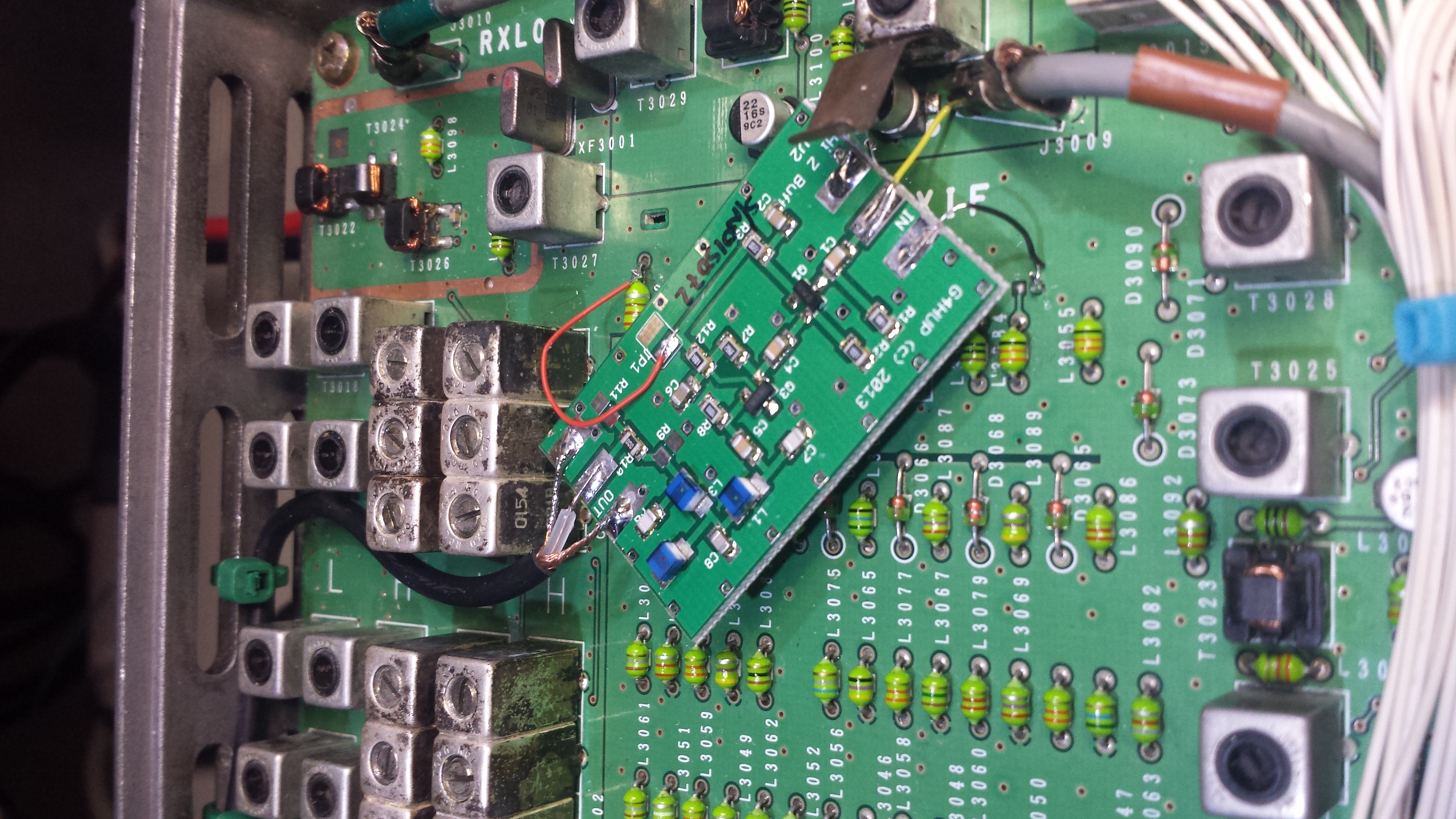
I used some short lengths of wire-wrap wire and some double-stick tape to integrate the amplifier in my radio.

The FT-847 uses a 45.7MHz IF frequency. This is a bit above the range of the SoftRock SDR receivers I own and below the range for my regular RTL820-based SDR receivers. However, the RTL820T2 receivers will go down in range that far.
This page last modified Thu May 19 09:30:03 CDT 2016 by timc!