This page captures my notes on a recent modification of a Radio Shack HTX-10 10M AM/FM/SSB transceiver for use as an IF radio with a Down East Microwave 222-28 transverter. The service manual for the HTX-10 is available on the web but the schematic is mostly unreadable. Fortunately schematic for the HTX-10 is identical to the Albrecht Electronics AE 485S, for which a very nice pdf is available. Both documents are available online with a little searching via Google.
This conversion is straightfoward and results in separate TX and RX connections along with PTT output. The final PA transistors are disconnected and TX output power is reduced to a level appropriate for a transverter. Conversion back to conventional 10M radio operation should be quick and simple.
This conversion was inspired by the article on the Down East Microwave website by Rus Healy, NJ2L titled Make your HTX-100 a Flexible IF Transceiver.
The conversion is accomplished with the following steps
- Back panel modification for additional connectors
- Disconnect voltage to final PA
- Disconnect PA from driver
- Attach TX BNC to circuit board
- Install PTT circuit
- adjustment
back plate modification
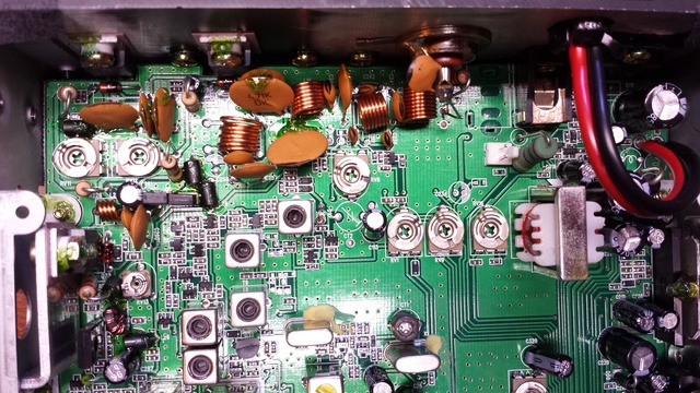
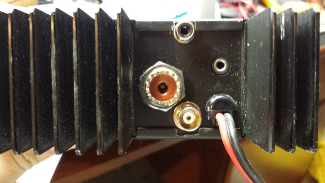
Carefully drill holes in the rear heatsink for two additional connectors;
one for PTT output and one for TX power output. I selected a BNC connector
for TX power output and an RCA female connector for PTT. There is just enough room on the
component side of the main board near the SO239 connector for a BNC.
There was room for the RCA connector on the solder side of the board.
Prior to drilling be sure to test for adequate clearance with a PL259 mated to the SO239 jack.
It may be necessary to notch the covers for best fit.
disconnect voltage to final PA
There are two 1/10" jumpers near marked "CON1" the rear of the main PC board.
Remove the right-most jumper, this is the one nearest L24. This jumper supplies voltage to
the final amplifier transistors. Leave the left-hand jumper in place. This supplies
voltage to the amplification stage prior to the final transistors.
disconnect PA from driver
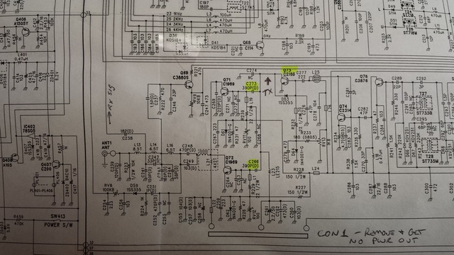
Unsolder capacitors C273 and C266. These connect the base of the
final PA transistors Q71 and Q72 (2SC1969) to Q73 (2SC2166), see schematic
above. These 290pF capacitors are located between CON1 and the rear heatsink
on the radio.
Attach TX BNC to circuit board
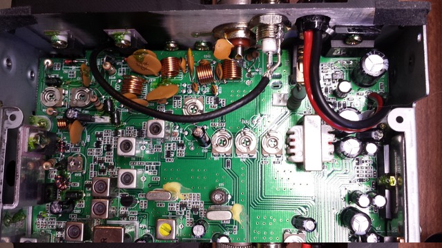
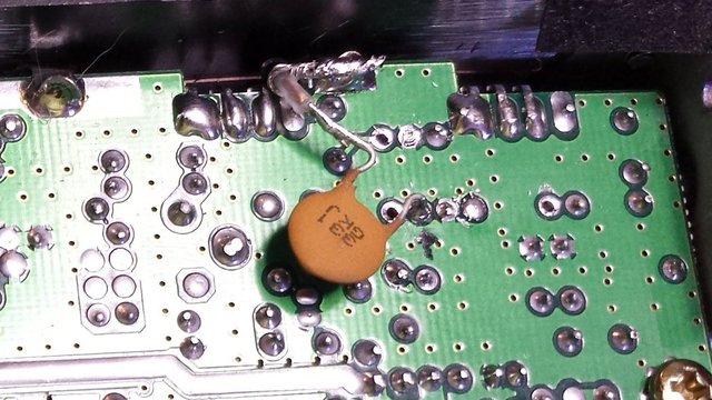
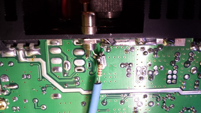
Use thin-gage coax (RG174 or similar) to attach the new TX power
output BNC. I attached on the solder side of the board through a
series 330pF capacitor to block any DC. The coax was easily routed
between the main PC board and the heatsink to reach the new BNC
connector. I opted for this routing because it was easy to solder
the coax shield to a ground near the edge of the PC board.
install PTT circuit
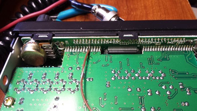
Locate a point on the front panel that provides a positive signal
during ptt. There are several solder bridges that attach the front
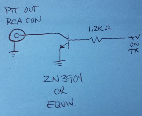
and main PC boards -- on the solder side I used connection number 10.
That is attached to the base of a 2N3904 transistor through a 1200
ohm resistor -- both were handy on my workbench.
adjustment
You can now adjust power output levels using RV13 on the main PC board.
This is located near CON1. I found that in FM mode I was able to get
between +24dBm and +28dBm output. Removing all CON1 jumpers lowered the
power output to between +0.2dBm and +2.6dBm. I would suggest measuring
the output levels to ensure compatability with your hardware.
I understand there are other adjustments that can be done for FM modulation level, AM modulation level, etc -- I left mine alone. The points to tweak are available in the service manual and from other sources online.
This page last modified Wed Aug 28 10:33:05 CDT 2013 by timc!
