I acquired a used Motorola R2200 -- the case has seen better days but the electronics appeared to be in good shape. The frequency generation and counting appeared to be very accurate when compared against my HP5345 using a GPS-disciplined reference oscillator and power measurements seem accurate.
But after leaving it on for a while -- an hour or so -- I found that the unit was all of a sudden dead. The input fuse was blown, so I replaced it. Blown instantly.
What I'm finding is what you might expect of 80s vintage hardware, the caps have seen better days.
This unit has a simple switching power supply to provide the +/-5,12 and +33v the unit needs. At first check the switching transistor is completely shorted and the rectification diodes are open-circuit.
So, digi-key to the rescue with a complete set of new capacitors and replacement diodes and transistors. I hope to have it back to 100% soon.
Mon Sep 10 22:32:52 CDT 2012
No such luck. New caps and transistors -- nothing. But at least I'm no longer popping fuses.
After troubleshooting it seems that the switching power supply IC, a TDA4718A may be suspect -- the Q output was switching as expected and indicated on the schematic. The Q' output was not doing the opposite -- it just hovered around 10V.
The TDA4718 is obsolete. Has been for a while. Found one in China from an old parts warehouse, utsource.com. Real? Counterfeit? Well, not available anywhere else. At $4 plus $4 shipping from China, it's worth a try.
With the new chip the unit is once again instantly blowing fuses. Maybe that's a good sign? Or maybe a sign that I better order more fuses...
Mon Oct 8 21:02:59 CDT 2012
The new switching supply chip appears to be working, Q and Q' are complementary. Unit still doesn't work.
Because I wasn't having any luck with the AC input, I opted to try DC input and see if that worked any better. What I see watching the +5V line is that it tries to come up to voltage, gets to around 3.8V and then cuts out.
A several things can cause the supply to stop. Over/under voltage, and over current. I think I'll next try pulling the individual boards to see if it powers up with minimal load.
Mon Oct 15 00:06:21 CDT 2012
Considered pulling all of the boards to see if the unit had some sort of overcurrent problem. Started with the internal oscilloscope module. No loss as the tube is shot anyway. Amazingly the unit powers up with the 12VDC input. Went through the section in the manual to set the over/undervoltage limits and set the +5V output appropriately.
This narrows down the problems with the power supply to a very small section with few components. Current draw is around 3 or 4 amps at 13.8V.
Saturday Oct 20 -- midnight or so Still thinking about this. The only components that are not shared with the 12V section are the HV switching transistors. The only parts that were not replaced were the fast snubber diodes because I couldn't find a direct replacement. But apparently most switchers circuits are identical -- you need a fast-recovery high voltage diode here. I can't find a direct substitute for CR5/CR6 which are Motorola pn 48-80390A74. The PR1007 diodes are commonly used in other switchers so I'm trying these. I think also the BUL128D (with diode) may also work for the transistor and eliminate the need for the diodes on board.
Yeah, still doesn't work. So down to approximately five components that are bad? Reading, looking and measuring more the TDA4718 looks to shut down briefly (within one second) after turn-on. There's a lot of control circuitry that can cause the shutdown for various reasons. I'm trying to decide where to start testing there.
More work on this later.
Wed Apr 10 00:09:06 CDT 2013
I give up.
Ok, it's not as drastic as it sounds. I think it's a good thing.
For now, I consider the repair of the original switching power supply to be beyond my capabilites and supply of parts. Without a board extender it's hard to even troubleshoot the damn thing. So I purchased a MicroSFX PC power supply -- an Athena Power Apollo 400 from newegg.com for about $20. The size is such that it will mostly fit in the space vacated by the old power supply. Unique to this supply is that it also provides a -5vdc output, not required by current ATX standards. I have a stub of a board ready to insert where the old R2200 power supply went and a header that will directly plug into the PC power supply. We'll see.
What I don't have is the +33v but as far as I can tell that only goes to the HV switching for the scope which isn't working anyway.
Thu Apr 11 23:41:16 CDT 2013
The new PC power supply has been stubbed in for the old supply and so far, success! The unit powers back up and appears to almost work. A revisit of the schematic indicates that I *do* need to supply +33v for the RF generator section which also supplies a 10.7MHz signal to the rest of the unit. So, off to do something about a +33V supply...
Fri Apr 19 13:43:56 CDT 2013
I acquired a cheap boost converter (Chinese ebay special...) to make +33V out of the +12V. I set the converter to +30V as the regulator in the RF module is +28V so that should be enough.
With the 33V converter in place it works!
Now back where I left off in September. Clean up some of the pots, clean up the case a bit and make the new power supply fit inside.
Fri May 10 11:37:16 CDT 2013
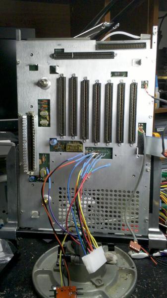
To best fit the MicroSFX power supply I decided to remove the original switching power supply cage from the chassis. This cage was attached via 7 or 8 rivets -- best way was to drill it out. Best way to drill safely, without leaving any aluminum bits behind is to completely disassemble the unit. Disassembly also provides an excuse to clean 30 years of fine dust and grit off everything. So, I pulled all the boards, static-bagged everything, made a bunch of notes, removed a bunch of screws and finally was able to remove the bottom backplane.
Decided to hard-wire the connector for the power supply. I'm really not going back now. The wires on the motherboard connector are larger than what fits in the vias on the backplane so I installed short jumpers of reasonable gage and then connected to the 24-pin PC power supply header with soldered connections dressed with heat-shrink.
The unit is now mostly assembled, waiting on some time for making a few aluminum plate inserts to blank the original power supply opening and secure the new power supply.
Tue May 21 11:35:19 CDT 2013
Found time this last weekend to make said plates. The PC power supply is installed in the back, the 33V boost converter is installed, the supply is wired up and the unit has been re-assembled. Good news is that it seems to work just fine with the new power supply. No bad news.
Now for the project to lower the level of the damn beeping when you press a keyboard key (ok, one resistor change) and to replace the scope module with something different.
Fri Jun 7 10:00:16 CDT 2013
Press a key, get a beep. Fine. But does that beeping need to be loud enough to wake up the kids? The counter board controls the beep generation on this unit from a 1kHz line from off-board. In-line is a 5.6kohm resistor...after some trial and error that was replaced with a 56kohm resistor. Much better!
On a related note, the skins are back on the unit with all of the screws in the holes and it's in a more or less permanent home on my workbench. I actually used the unit for testing the other evening! I needed to generate a couple of test signals and wanted to measure the power of a UHF radio. Worked perfectly.
This page last modified Fri Jun 7 10:00:12 CDT 2013 by timc!