Section#7: Routing algorithms and switching techniques
(CS838: Topics in parallel computing, CS1221, Tue, Feb 16, 1999, 8:00-9:15 a.m.)
The contents
- Taxonomy of communication problems
- Basic concepts
- Taxonomy of one-to-one routing algorithms
- Basic switching techniques
- Circuit switching (CS)
- Store-and-forward (SF) switching
- Virtual cut-through (VCT) switching
- Wormhole (WH) switching
Taxonomy of communication problems
Communication problems can be classified into several classes according to the number of source and destination nodes and the way how the transfered information is handled.
- One-to-one communication:
- Information is only exchanged (not duplicated) between one or several pairs of nodes.
- single-pair communication: there is just one isolated communicating pair. There are no problems with deadlocks, congestions, and so on. The basic algorithms for shortest path routing in usual interconnection networks were described in Section 5. In this section, we will describe basic switching techniques for these routing algorithms.
- many one-to-one communications: several pairs exchange information simultaneously. This section covers switching techniques and flow control methods in such a case.
- permutation routing: every node is a source of one message and a destination for another message at the same time. This communication pattern implies a permutation among nodes. Sections 9 and 10 will describe algorithms for permutation routing.
- One-to-many communication:
- One node is the sender and several or all nodes are receivers. If the same information is disseminated in multiple copies among the other nodes, these patterns are known as multicast and one-to-all broadcast communication operations. If the information sent to each destination node is different, the pattern is called one-to-all scatter. Section 11 and 12 are devoted to these two problems.
- All-to-all communication:
- This can be again all-to-all broadcast or scatter and Sections 13 and 14 will describe some algorithms for these patterns.
One-to-many and all-to-all patterns are called collective communication operations.
Basic concepts
Router architecture
- processing node:
- standard bus-based computer augmented with a router.
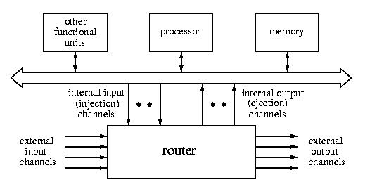
CAPTION: Generic structure of a processing node
- router:
- a HW coprocessor implementing lower levels of communication protocol. It comprises of a switch, buffers, and routing and arbitration unit (see Figure 1 ).
- external channels:
- interconnect routers and define the topology of a connected direct interconnection network.
- adjacent nodes:
- nodes with directly connected routers.
- internal channels:
- connect the router to the local processing node and implement the physical HW interface between them.
- 1-port architecture: one injection and one ejection channel (as in Figure 2),
- k-port architecture: k injection and k ejection channels,
- all-port architecture: # of injection channels = # of external output channels
and # of ejection channels = # of external input channels.
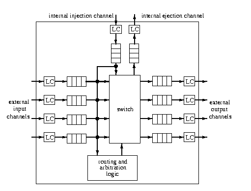
CAPTION: Generic architecture of a 1-port router with input and output buffering. LC = link controller.
- channel:
- consists of buffers, link controllers, and communication medium (e.g., coax cable).
- buffer:
- FIFO memory for storing one or several units of communication in transit. They are required for storing transfered data until the next channel is reserved and can overtake them. A router can implement
- input and output buffering: each input and output external channel is associated with one buffer, as in Figure 2.
- input buffering: buffers are associated with input external channels only,
- output buffering: buffers are associated with output external channels only.
- message:
- the unit of communication from the programmer's perspective. Its size is limited only by the user memory space.
- packet:
- fixed-size smallest unit of communication containing routing information (e.g., a destination address) and sequencing information in its header. Its size is of order hundreds or thousands of bytes or words. It consists of header flits and data flits.
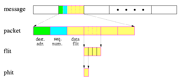
CAPTION: Communication units.
- routing and arbitration unit:
- implements the routing algorithm and packet flow control protocol and sets the switch accordingly. For example, it resolves conflicts between simultaneous requests for the same output link (typically using some round-robin, fixed channel priority, or first-come-first-serve policy).
- routing algorithm:
- determines the path selected by a packet to reach its destination. It must decide within each intermediate router which output channel(s) are to be selected for incoming packets.
- switch:
- interconnects input buffers to output buffers (channels). It can be either crossbar providing full connectivity or some cheaper substitute providing partial connectivity.
- switching mechanism:
- determines how network resources are allocated for data transmission, i.e., how and when the input channel is connected to the output channel selected by the routing algorithm. It is the actual mechanism that removes data from input channels and places them on output channels.
- flow control:
- defines the synchronization protocol between sender and receiver nodes which determines actions to be taken in case of full buffers, busy output links, faults, deadlocks, etc. Flow control has at least two levels.
- packet flow control: performs synchronization between sender and receiver at the level of packets, ensuring successful transfer and availability of buffer space at the receiver. Flow control deals with allocation of channels and buffers to a packet as it travels along a routing path. It guarantees that either sufficient buffering is provided by the receiver and the packet can proceed or a resource collision is handled. There is a variety of resource collision protocols. The packet that cannot proceed since the output channel required by the routing algorithm is not available, can be for example:
- stopped until sufficient buffer space becomes available. Until then, the resources along the current path are blocked (wormhole switching),
- buffered in local router buffers (virtual cut-through, store-and-forward switching),
- rerouted (adaptive routing),
- killed.
- physical channel flow control: implements the multicycle packet flow control above. It breaks packets into flits. But even flits may take several cycles to transfer, hence the most elementary unit of information is phit.
- link controller:
- (LC) implements the physical channel flow control communication protocol between neighboring routers (such as handshaking).
- flit:
- small unit of information at link layer, of size of one or several words. Flits can be of several types and flit exchange protocol typically requires several cycles.
- phit:
- the smallest physical unit of information at the physical layer, which is transfered across one physical link in one cycle.
Taxonomy of one-to-one routing algorithms
- Routing decisions:
- The most important criterion for routing is where and when is the routing function determined.
- distributed routing:
- the routing function is calculated in routers or nodes as packets travel across the network. Headers contain only destination address, used by routers to select output channel(s). Each router knows only its neighborhood, since the designer has encoded the whole topology distributively into individual routers. Distributed routing is especially favorable in symmetric or regular topologies, since all routers use the same routing algorithm.
- source routing:
- source nodes predetermine complete routing paths before injecting packets into the network so that routers only read the headers (and usually cut off or mark appropriate subfields in the header) and mechanically set its switches accordingly. If the output degree of a router is k, then the header of a packet following a path of length d requires at least dlog k bits for encoding d output channel numbers. This scheme is used in IBM SP-2 machine. In networks based on cartesian products, the size of the header routing information can be reduced by using so called street-sign routing. The default output channel is of the same dimension and direction as the input channel, unless the header starts with explicitly given new output channel number associated with an address which matches the address of current router.
- hybrid (multiphase) routing:
- the source node precalculates only addresses of some intermediate nodes and the precise paths between them is determined in a distributed manner by routers. This option was implemented for example in nCUBE-2 machine. It assumes that routers consecutively cut off intermediate node addresses.
- centralized routing:
- the routing function is determined by a centralized controller. This has been used typically in SIMD machines.
- Implementation of routing algorithm:
- Routing decisions should be fast. In case of distributed routing, a HW implementation is desirable. There are two basic approaches.
- finite-state machine:
- HW or SW algorithm implementing some finite-state automaton.
- table lookup:
- source nodes and/or routers keep routing tables. The number of entries is O(N), where N is # of nodes in the network. Source node routing tables contain the whole path specifications, whereas in case of distributed routing the lookup tables just say which output channel(s) correspond(s) to every destination. To decrease the linear table size, so called interval routing can be used, see Subsection .
Routing tables can be either static or dynamically maintained. An example of a system with dynamically updated lookup tables is Myrinet, which allows automatic recomputation of routing tables whenever the interconnection network changes, for example, due to deleting a node.
- Adaptivity:
- Routing decisions can be based not only on the addresses, but also on other information.
- deterministic routing algorithms
- always generate the same single routing path for given pair of source and destination addresses, typically a shortest one. When source routing is used, the source node implements pure routing function returning a unique path without considering any information about the traffic. For distributed routing, routers make unique decisions in every intermediate node. Deterministic distributed routing is used in most commercially available parallel machines. It is simple, fast, and performs well under uniform traffic assumption. In mesh-based machines, it is the dimension-order routing (XY, XYZ, e-cube). It is known to be deadlock-free in meshes and is easy to implement in HW. Nonuniform traffic requires some degree of adaptivity.
- oblivious routing algorithms
- do not take into consideration any other information except the addresses, equally to deterministic routing. The routing decision are oblivious to the status of network traffic. Any deterministic routing is oblivious, but oblivious routing is not necessarily deterministic. For example, there may exists several shortest paths between the source and destination and the routing algorithm selects
one of them. Oblivious nondeterministic algorithms can distribute uniformly the communication load in situations where adaptive solutions are too expensive or slow.
- adaptive routing algorithms
- use information about network traffic and/or channel status to avoid congested or faulty regions of the network. Source-node adaptive routing is useful only when the traffic status does not change too fast, otherwise the source node may have obsolete information and a global status is costly to monitor. On the other hand, adaptive routing can easily be combined with distributed routing, since routers can react on local congestions using some heuristics, history tables, or probing the neighborhood. Sometimes a simple randomized decisions of ``hot-potato'' type suffice to avoid blocking due to busy output channels (Chaos router). While being able to avoid deadlocks, adaptive routing must take care of livelocks. Adaptive routing can be decomposed into two functions:
- routing function,
- which delivers a set of possible output channels,
- output selection function,
- which selects one of free output channels among them (if such exists) using local status information.
- Minimality:
-
- greedy algorithms:
- (also called minimal, direct, shortest-path, or profitable.) Every routing decision brings the packet closer to the destination. Deterministic and oblivious routing algorithms are usually greedy.
- nongreedy algorithms:
- (also called nonminimal, indirect, nonprofitable, or misrouting.) They can supply channels which send packets away from its destination. This is used exclusively in adaptive routing. It is an optimistic approach: instead of waiting in case of blocking, we believe that a longer detour will bring us into a free region where we can resume greedy routing. However, it consumes additional resources and is prone to livelocks.
- Progressiveness of routing:
-
- progressive adaptive routing:
- Each routing operation allocates a new channel and the length of the route path increases, of course not necessarily bringing the packet closer to the destination. Greedy routing is always progressive.
- backtrack adaptive routing:
- The header is allowed to backtrack, releasing previously reserved channels. This is used mainly in fault-tolerant routing when no alternative progressive continuation is possible. It assumes history information to ensure that the same paths are not tried repeatedly. Backtrack is hard and costly implement in wormhole switching, in contrast to circuit switching. Backtrack routing cannot be deterministic.
Interplay between interconnection networks and routing algorithms
Given an interconnection network with given topology, its ability to serve as an efficient and reliable communication medium for transferring messages between nodes depends on the level to which the routing algorithm can exploit its structural properties. This concerns namely:
- adaptivity: ability to use the path redundancy of the topology for rerouting packets in case of contention or congestion at links, nodes, or regions.
- fault tolerance: similar to the previous property, even though fault tolerant routing need not be necessarily adaptive. It can be achieved for example by storing packets in intermediate nodes and by routing them in more phases.
- deadlock freedom: some topologies are known to have deadlock-free routing algorithms.
Interval lookup table routing
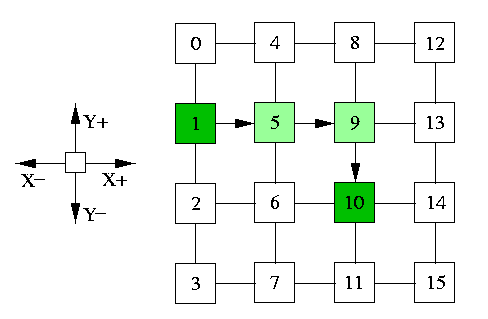
Simple routing tables have size O(N), where N is the number of nodes in the network. This can be a limiting factor either due to excessive memory requirements or due to larger routing latency. Interval routing allows to decrease the lookup tables size by requiring only one entry per output channel. Each entry contains an interval of destination addresses, specified by two bounds. Optimal interval routing schemes are still an active research area. One important question is, for example, whether for given topology only one interval per channel allows shortest path routing. The problem is solved in case of 2-D meshes. If we use node labeling as indicated in Figure 4, there exists 1-interval routing scheme implementing shortest-path XY routing, as can be easily checked in case of the 4× 4 mesh in the figure.
The lookup tables are shown only for nodes 1, 5, and 9.
|
|
|
node | channel | interval |
|
1 | X+ | 4-15
|
|
| Y+ | 0- 0
|
|
| Y- | 2- 3 |
|
5 | X+ | 8-15
|
|
| X- | 0- 3
|
|
| Y+ | 4- 4
|
|
| Y- | 6- 7 |
|
9 | X+ | 12-15
|
|
| X- | 0- 7
|
|
| Y+ | 8- 8
|
|
| Y- | 10-11 |
|
|
CAPTION: Optimal 1-interval routing scheme implementing XY routing in 4× 4 mesh
Basic switching techniques
Performance metrics
- channel width w:
- # of bits that a physical channel can transmit simultaneously between two adjacent routers. Clearly, it is exactly the size of a phit.
- channel rate \mu:
- the peak rate in bits/second at which bits can be transfered over each individual wire of a physical channel.
- channel bandwidth B:
- B=\mu in phits/second, even though it can be defined also as B=w× \mu in bits/second.
- channel latency tm:
- the inter-router latency of one phit, hence tm=1/\mu=1/B in seconds/phit.
- bisection bandwidth B(G)
- of a network G: B(G)=B× bwe(G)
- startup latency ts:
- the time required for packet framing/unframing, copying data between memory and router buffers, validation and so on, at both source and destination side. It depends mainly on the design of system SW, on its interface to user programs, and on the physical interface between processing nodes and routers. It is a static value, independent of network traffic or distance between nodes. It depends only on the size of the message.
- network latency:
- the elapsed time after the head flit of a packet has entered the network at the source router until the tail flit is ejected. The network latency consists of two components: a conflict-free packet transmission time, which strongly depends on the switching technique, and the blocking time, which includes all possible delays encountered during the lifetime of a packet.

CAPTION: General time model of a conflict-free communication between distant nodes
In the following subsections, we will describe 4 main switching techniques used in multiprocessor networks. We will not be mentioning startup time ts, since it is a static component common to all 4 techniques. Instead, we give formulae for the conflict-free network latency, i.e., assuming a network without any other traffic. We will call this latency the base communication latency. For simplicity, we assume that each packet has only one header flit. We will use the following notation in this section and throughout the rest of this course:
- w = flit size = phit size = channel width (in bits),
- M = packet size (in flits),
- tr = time of routing decision within one router during building a routing path (in seconds),
- tw = intra-router switching latency once the router has made the routing decision and a path has been set up through the router (in seconds/phit),
- tm = 1/B = inter-router channel latency (in seconds/flit). The transmission latency of a packet of M flits between two adjacent routers is Mtm seconds.
- d = the length of a routing path.
Circuit switching (CS)
- The communication between a source and destination has two phases: circuit establishment phase and message transmission phase.
- A physical path from the source to the destination is reserved prior to the transmission of data by injecting a routing probe, which contains destination address and some control information. It usually needs more that one phit. Let p be the size of the probe in phits.
- The probe progresses towards the destination node, reserving physical links as it is transmitted through intermediate routers (see Figure 5(a)).
- The path is set up after the probe has reached the destination.
- Then an acknowledgment flit is sent back (see Figure 5(b)).
- Upon reception of the acknowledgment, the sender transmits the whole message at the full bandwidth of the path.
- The path froms a HW circuit that is reserved for the whole time of the message transmission (see Figure 5(c)).
- The circuit is released either by destination node or by the last bits of the message.

CAPTION: Circuit switching on a path of length 3. (a) The probe progresses towards the destination router. (b) The acknowledgment is sent back to the source. (c) The whole message is transmitted along established circuit using its full bandwidth.
Base communication latency
A message of length M transmitted to distance d takes time
tCS=d(tr+(p+1)(tw+tm))+Mtm
The probe needs time d(tr+p(tw+td)) to get to the destination, the acknowledgment takes d(tw+td) to get back, and the data transmission takes Mtm.
Remarks
- It is advantageous if messages are infrequent and long, i.e. the transmission time is longer than the setup time. In case of short messages, the whole physical circuit is reserved during the whole setup and transmission part.
- While the probe is buffered at each router, the data bits are not. The circuit operates as a single wire form the source to the destination.
- Messages need not be broken into fixed-length packets, but can be transmitted as continuous flow of bits along the setup circuit. Hence, there are no limits on the length of transmitted data.
Store-and-forward (SF) switching
This technique is alternatively called packet switching.
- The message is split into fixed-length packets, every packet consists of flits, starting with the header flit.
- Every channel has input and output buffers for one entire packet.
- Every packet is individually routed from the source to the destination.
- One step of the SF switching is called hop. It consists of copying the whole packet from one output buffer to the next input buffer.
- Routing decisions are made by each intermediate router only after the whole packet was completely buffered in its input buffer.
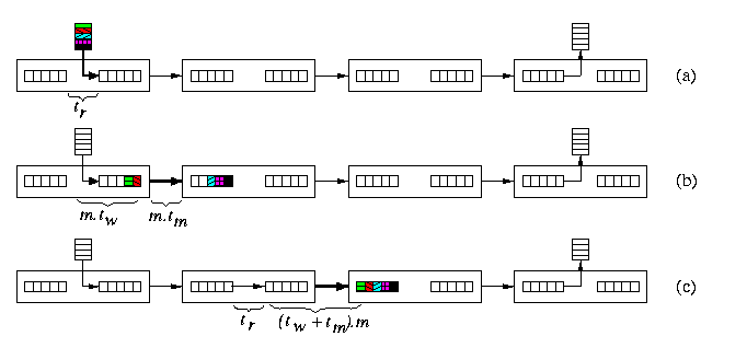
CAPTION: Store-and-forward switching of a packet. (a) Routing decision is being made in the first router. (b) The packet is performing the first hop to the second router after has been copied to the output buffer of the first router. (c) The whole packet after the second hop.
Base communication latency
A packet of length M transmitted to distance d takes time
tSF=d(tr+(tw+tm)M)
At every router, routing decisions must be made and then the packet hops to the next router, which takes tr+ (tw+tm)M, and this repeats d times.
Remarks
- This technique is advantageous, when messages are short and frequent, since one transmission makes busy at most one channel from the whole path.
- The need to buffer the whole packet makes either the router design expensive and/or slower, or the size of packets is limited.
- The communication latency is proportional to the product of packet size and distance. This forces designers to seek shortest path routing and use low-diameter networks.
Virtual cut-through (VCT) switching
This is the most sophisticated and expensive technique among the four introduced here.
- Messages are split into packets and router have buffers for the whole packet as in SF switching.
- Instead of waiting for the whole packet buffered, the incoming header flit is cut through into the next router as soon as the routing decision was made and the output channel is free (see Figure 6(b)).
- Every further flit is buffered whenever it reaches the router, but it is also immediately cut-through to the next router if the output channel is free (see Figure 6(c)).
- In case the header cannot proceed, it waits in the current router and all the following flits subsequently draw in, possibly releasing the channels occupied so far (see Figure 6(d)).
- In case of no resource conflicts along the route, the packet is effectively pipelined through successive routers as a loose chain of flits (see Figure 6(e)). All the buffers along the routing path are blocked for other communication requirements.
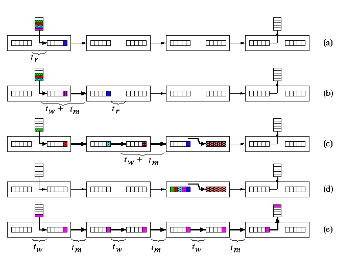
CAPTION: Virtual cut-through switching of a packet. (a) The header flit has moved into the output buffer of the first router. (b) The header has cut through into the second router while subsequent flits are following its path. (c) Pulling a chain of flits behind, the header has cut through into a router where its output buffer is reserved for another communication. (d) The whole chain of packet flits has contracted and the whole packet gets buffered in the first router releasing all previously allocated links. (e) Flit pipeline moving towards the destination.
Base communication latency
A packet of length M transmitted to distance d takes time
tVCT=d(tr+tw+tm)+max(tw,tm)M
We assume that there is no time penalty for cutting through. Only the header experiences routing delay as well as switching and inter-router latency. Once the header flit reaches the destination, the cycle time of the pipeline of packet flits is determined by the maximum of the switching time and inter-router latency. This is because we assume that channels have both input and output buffers. In case of input buffering only, for example, we would have tw+tm instead of max(tw,tm).
Remarks
- Only the header flit contains routing information and therefore each incoming data flit is simply forwarded along the same output channel as its predecessor. Therefore, transmission of different packets cannot be interleaved or multiplexed over one physical channel.
Wormhole (WH) switching
- The packets are split to flits which are snaked along the route exactly in the same pipeline way as in conflict-free VCT switching. Hence, also here transmission of different packets cannot be interleaved or multiplexed freely over one physical channel without additional architectural support.
- The main difference is that routers do not have buffers for the whole packets. Instead, every router has small buffers for one or a few flits.
- The header flit again builds a path in the network, which the other flits follow in pipeline. The sequence of buffers and links occupied by flits of a given packet forms the wormhole. However, the length of the path here is proportional to the number of flits in the packet. Typically, it spans the whole path between the source and destination.
- If the header cannot proceed due to busy output channels, the whole chain of flits gets stalled, occupying flit buffers in routers on the path constructed so far and blocking other possible communications.
- Conflict-free communication latency tWH is exactly the same as in VCT switching (see Equation ). Hence, it is proportional to the sum of the path length and packet size.
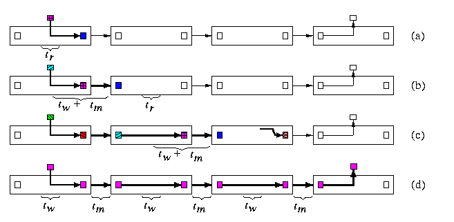
CAPTION: Wormhole switching of a packet. (a) The header is copied in the output buffer after having done routing decision. (b) The header flit is transfered to the second router and other flits are following it. (c) The header flit arrived into a router with busy output channel and the whole chain of flits along the path got stalled, blocking all its channels. (d) Pipeline of flits in case of conflict-free routing, establishing the wormhole across routers.
Remarks
- Wormhole routing allows simple, small, cheap, and fast routers. Therefore, it is the most common switching technique used nowadays in commercial machines.
- Wormhole routers use often only input buffering.
- Blocking resources in case of stalled pipelines is the main drawback of this technique.
- Since blocking chains of buffers can easily cause snow ball effect, WH switching is very deadlock-prone. Deadlock handling requires special care here and we will explain it in Section #8.
- This issue is related to the concept of virtual channels. As already mentioned, we cannot mix flits of different packets into one buffer (= one physical channel), since flits carry no identity flags. However, with adding some control logic, we can split one physical channel into several virtual channels. They will have their own buffers, but will share (time-multiplex) one single physical channel medium (similarly to processes with own contexts sharing one physical processor).
Summary
In the rest of this course, to calculate the total communication latency of message passing, we will consider the startup costs, but we will use simplified formulae derived from Equation 1 , 2 , and 3 . In typical parallel architectures, we have ts>> tm and tm\approx tw\approx tr. Therefore the following simplified expressions are good approximations of the exact formulae.
tSF = ts+dMtm
tVCT = tWH = tCS = ts+dtd+Mtm
where td=tr+tw.
Note this approximation allows to consider WH, VCT and CS as equally fast techniques. What makes the difference between SF and the remaining three is that SF latency is proportional to the product of distance and packet size, whereas the latter three techniques achieve latency proportional rather to a sum of both parameters.
Moreover, for larger M (say of order hundreds of flits), we usually have Mtm>> dtd in most parallel machines. Therefore, the base latency depends very little on the distance between the source and destination. In conflict-free situations, the distances do not matter. That is why VCT, SC, and WH are called distance insensitive switching techniques, whereas SF is distance sensitive.
Last modified:
Fri Jan 23 by tvrdik
|


