BioMesh User's Guide


Note:  The following guide is still under construction ... Hope to finish it soon.

Introduction

In this document, we provide a quick overview of Biomesh software from an user's perspective.  We hope that with this documentan user can :
  1. Quickly understand what this software can and can not do.
  2. What are the acceptable geometries models and input/output formats.
  3. How the quality of the outmesh mesh is controlled ?
  4. To what extend automation was possible.
  5. Current status and future plans.
We have provided some simple examples and datasets for experimentation. In this documents, we will not describe the time consuming process of image segmentation and registration. We assume that the user has acquired geometric information using other software tools which may be automatic, or semi-automatic.

Topologically Biomesh support the following tubular structures. 


SingleTube


   Bif1
Bif2
dual
Single Tube
Single Bifurcation
Multiple Bifurcation
Annular Geometry

Download Software and example dataset.

The very first to understand the software will be to download, source code and sample dataset from the following website.

                                http://www-unix.mcs.anl.gov/~csverma/BioMesh/biomesh.html

The source code is written in C++ and require some additional free software.

 Five easy steps to use the software.

  Using Biomesh software envolves five steps.
  1. Create a watertight triangulated surface ( Extend the geometry, if needed ).
  2. Classify vertices into surface, inlet and outlet.
  3. Solve the heat conduction problem(s).
  4. Use the default values for creating chips and then adjust the values to control the axial spacing.
  5. Create hexahedral mesh using mesh template on chip.
Converting raw images to a watertight model is perhaps the most time consuming part. Only step two and four would need some
user's judgement. 

Input Geometric Models and Parameters. 

The acceptable geometric model could be given in any of the following.

Boundary condition for heat conduction problem.

The boundary vertices are classified into three sets : Boundary, input and output

Boundary Vertices =  Input Vertices + Output Vertices +  Surface vertices.

In order to solve  heat conduction problem, at  least one  input and output vertices ( two for bifurcation geometries ) must be specified.  Except for simple geometries, it is difficult to get high quality chips near the inlet and outlet boundary, therefore, we recommend  extending the tube to some length. In general, we found that some heuritic or visualization might be better, quicker and easier than some algorithmic tools. (In our examples, we used  cuttoff in z direction to identify the inlet and outlet vertices ).

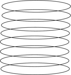
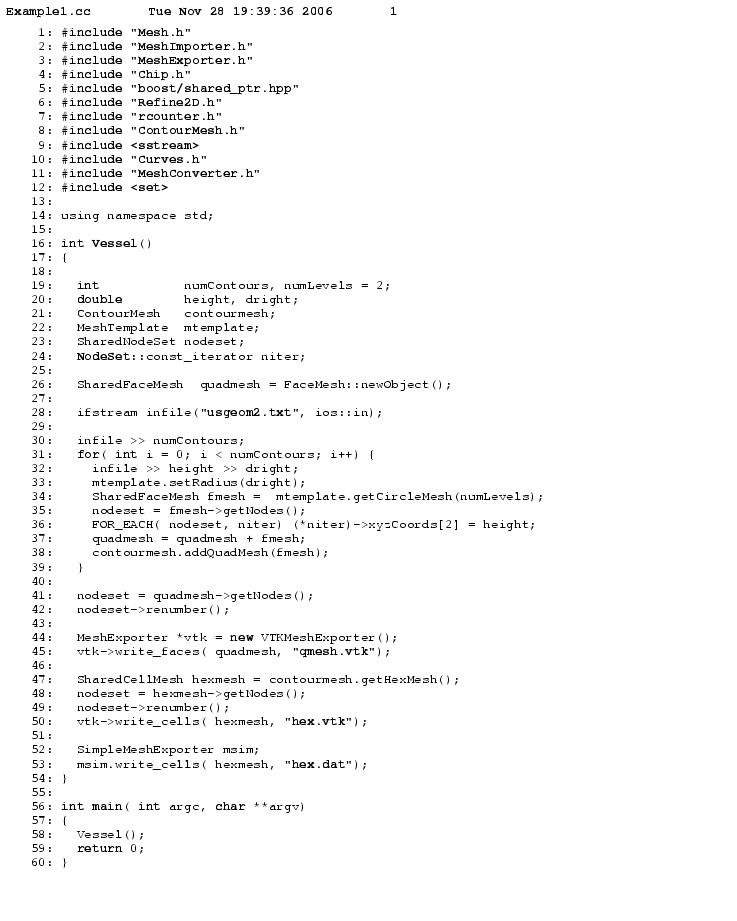
Example 1: Single tube geometry with planer contours ( Example1.cc )

This is the simplest example to demonstate the concept of mesh template and to demonstrate how quadrilateral mesh from two adjacent chips are used to create hex volume mesh.


Example1

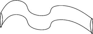
Curved single tube geometry  ( Example12.cc )


This example demonstrate the use of heat conduction equation to create non-intersecting chips that follows the chip geometry.

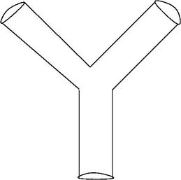
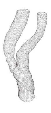
Example 2:Bifurcation Geometry


This is the main example to show the useful of our algorithm. In this example, we solve three heat condution problems with various boundary conditions as explained in the paper.

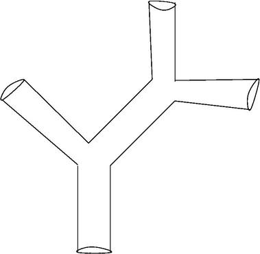
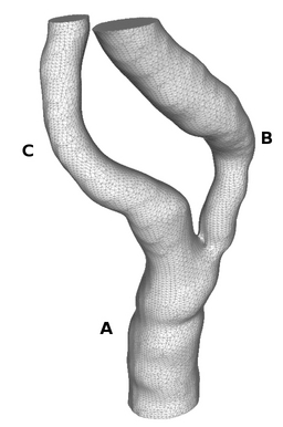
Example 3: Multiple Bifurcation Geometry

We extend the single bifurcation example to geometries with multiple bifurcations. The idea is to split the geometry into single bifurcation
geometries and the glue the resulting mesh. As you can guess, the crux of this geometry is to split the geometry and to ensure the quality of the mesh near the divided region.

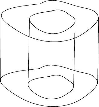
Example 4: Annular Geometry