Overview & Goals
I wanted a pocketable remote that could sleep most of the time, wake instantly, send a 433 MHz packet, and drop back into a low-power state on a coin cell. It also doubled as a crash course in PCB design, RF layout, and enclosure design.
- Learn PCB design and layout for a real battery-powered product.
- Hand place and solder SMD parts, then move to paste + stencil + hot air.
- Debug wake-up sources, sleep behavior, and RF performance.
- Design comfortable cases and iterate on the ergonomics.
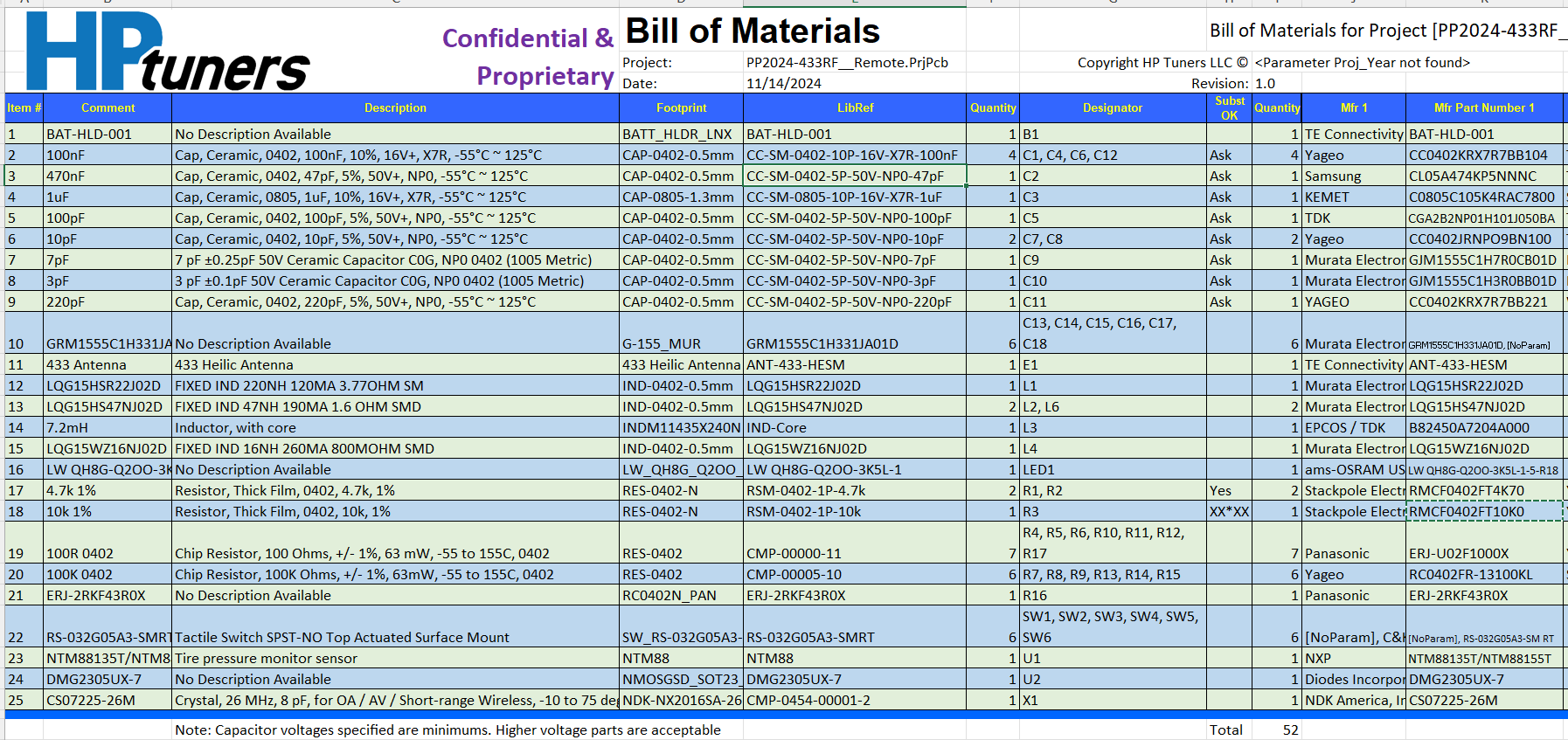
Parts & BOM
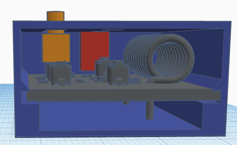
The board combines the MCU, RF circuitry, 125 kHz section, buttons, and a coin cell holder. The full BOM came out to around $300 including prototyping.
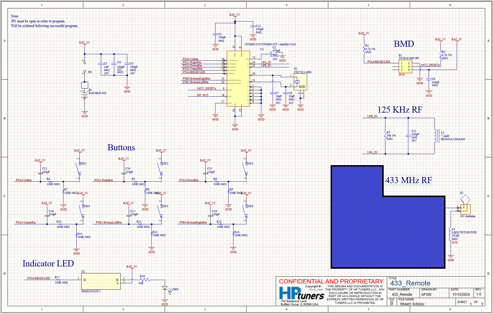
Schematic
The remote’s PCB hosts the RF front end, MCU, 125 kHz interface for future features, and all user buttons. I wanted a single compact board that could slide into different cases.
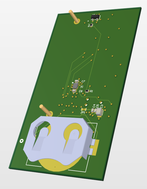
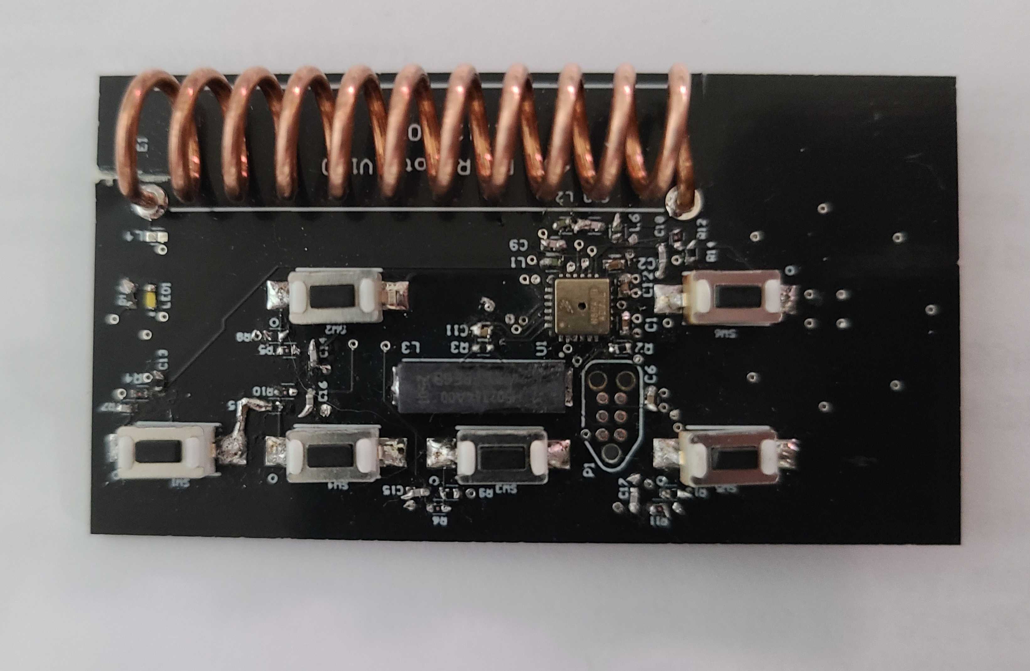
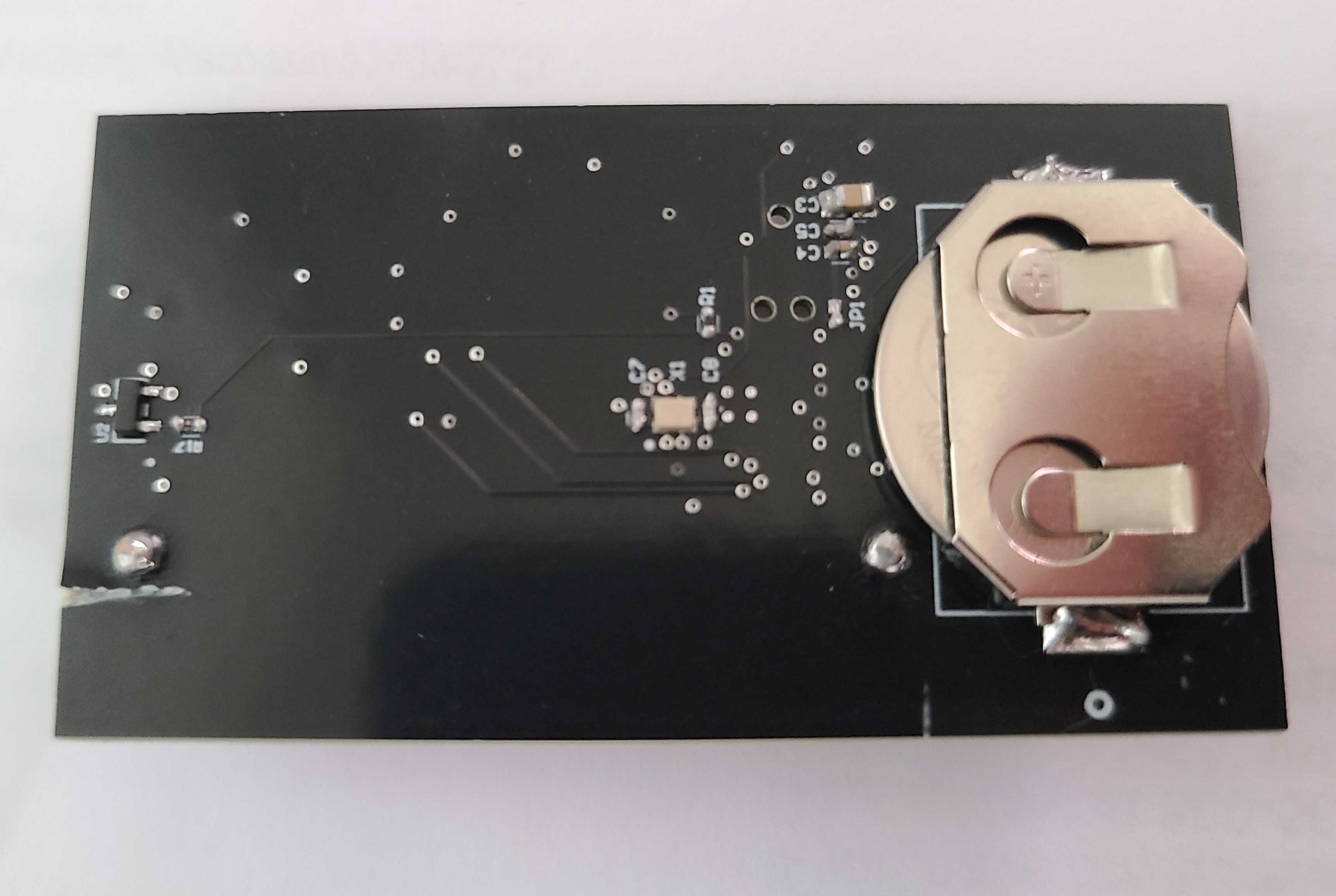
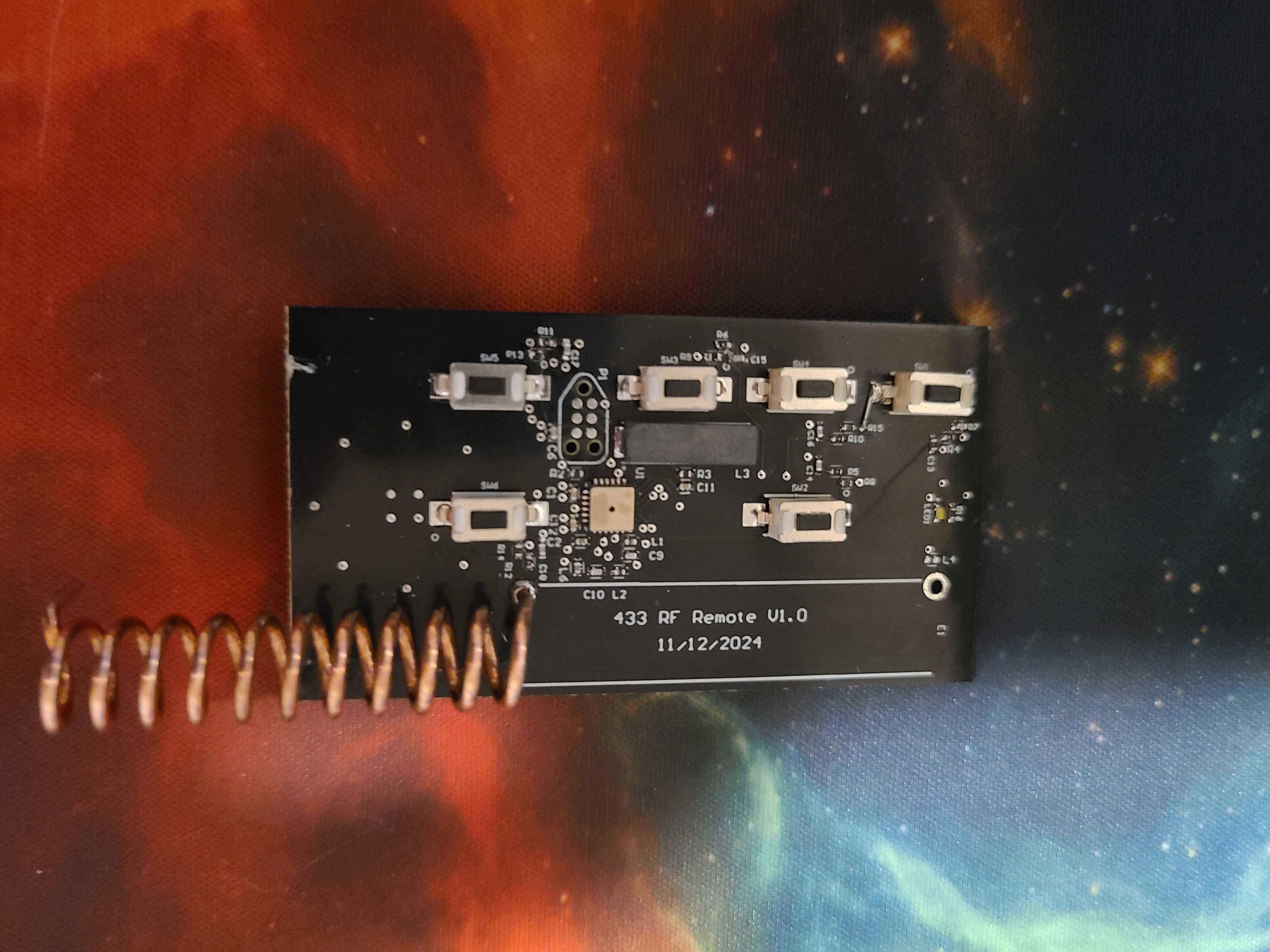
PCB
The remote’s PCB hosts the RF front end, MCU, 125 kHz interface for future features, and all user buttons. I wanted a single compact board that could slide into different cases.
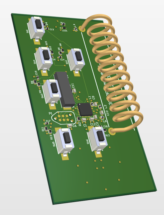
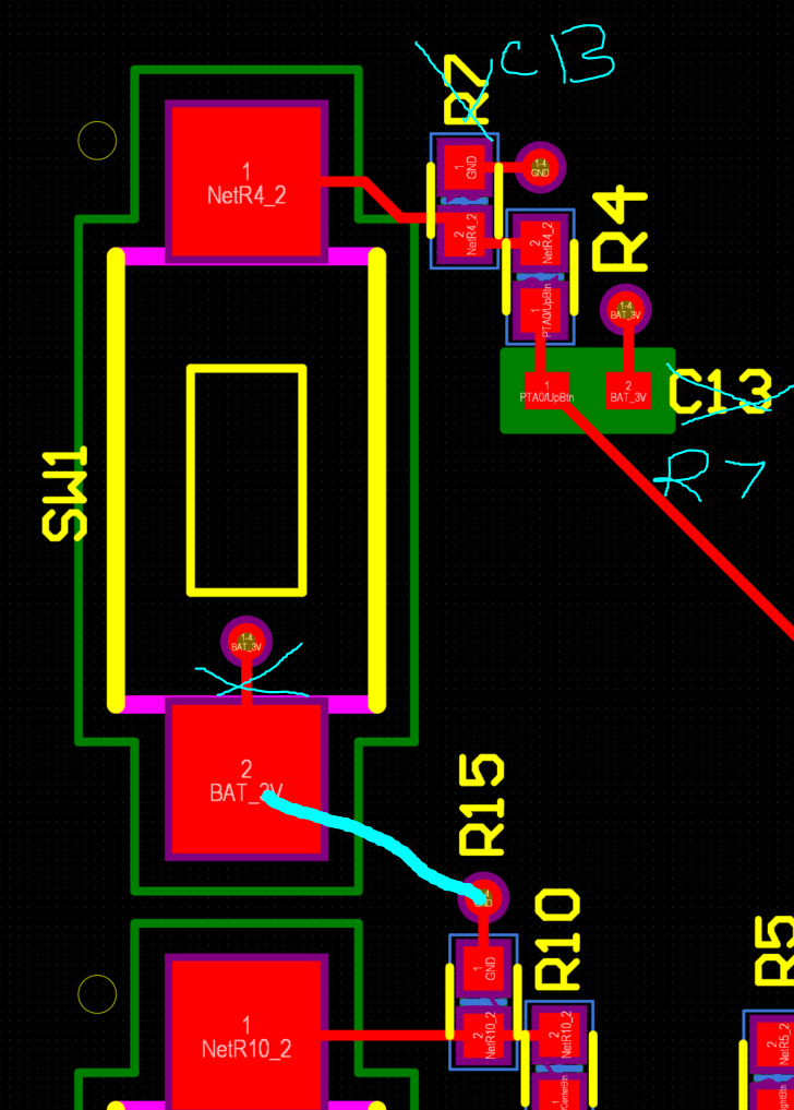
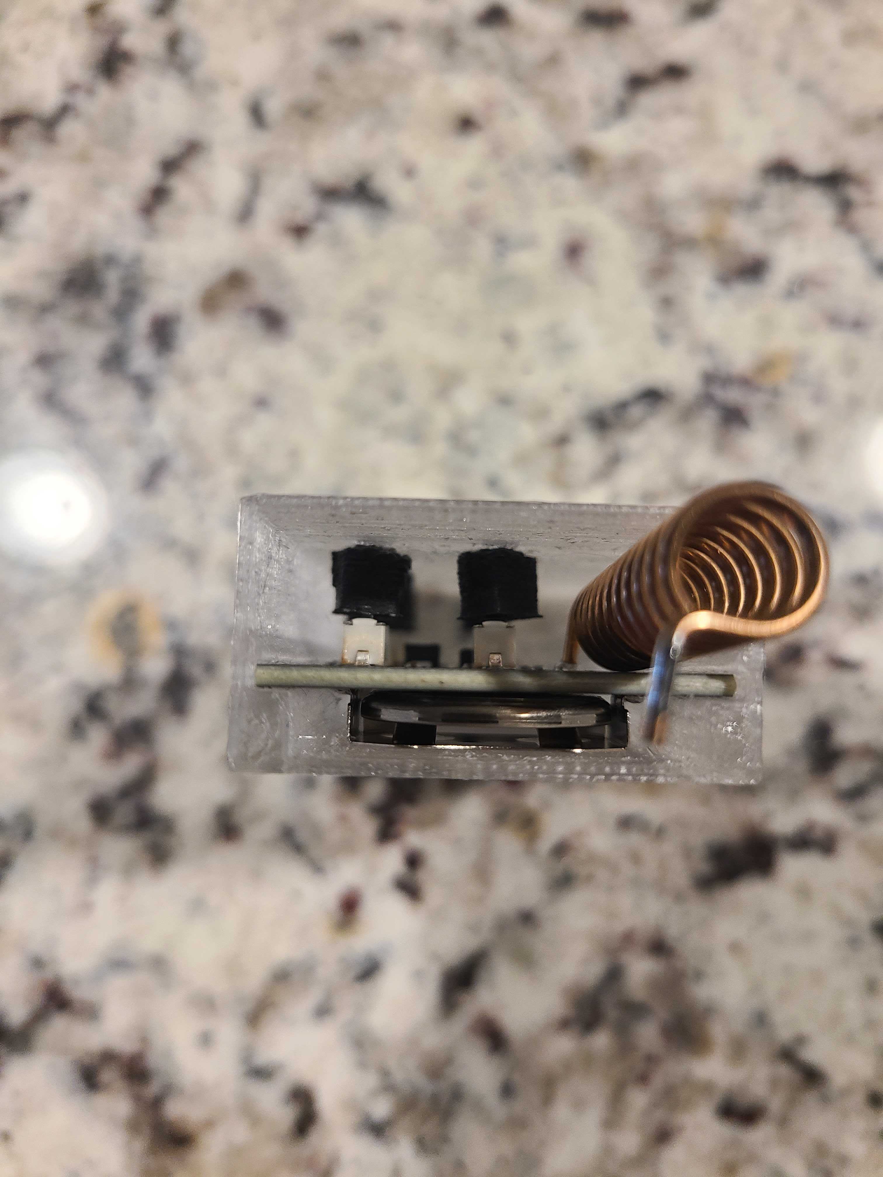
Fixes
Low power mode can only be woken up from a signal coming from 3v being pulled down to ground. Had to move the antenna from its original placing. The hand soldering job wasn't working great for the RF.
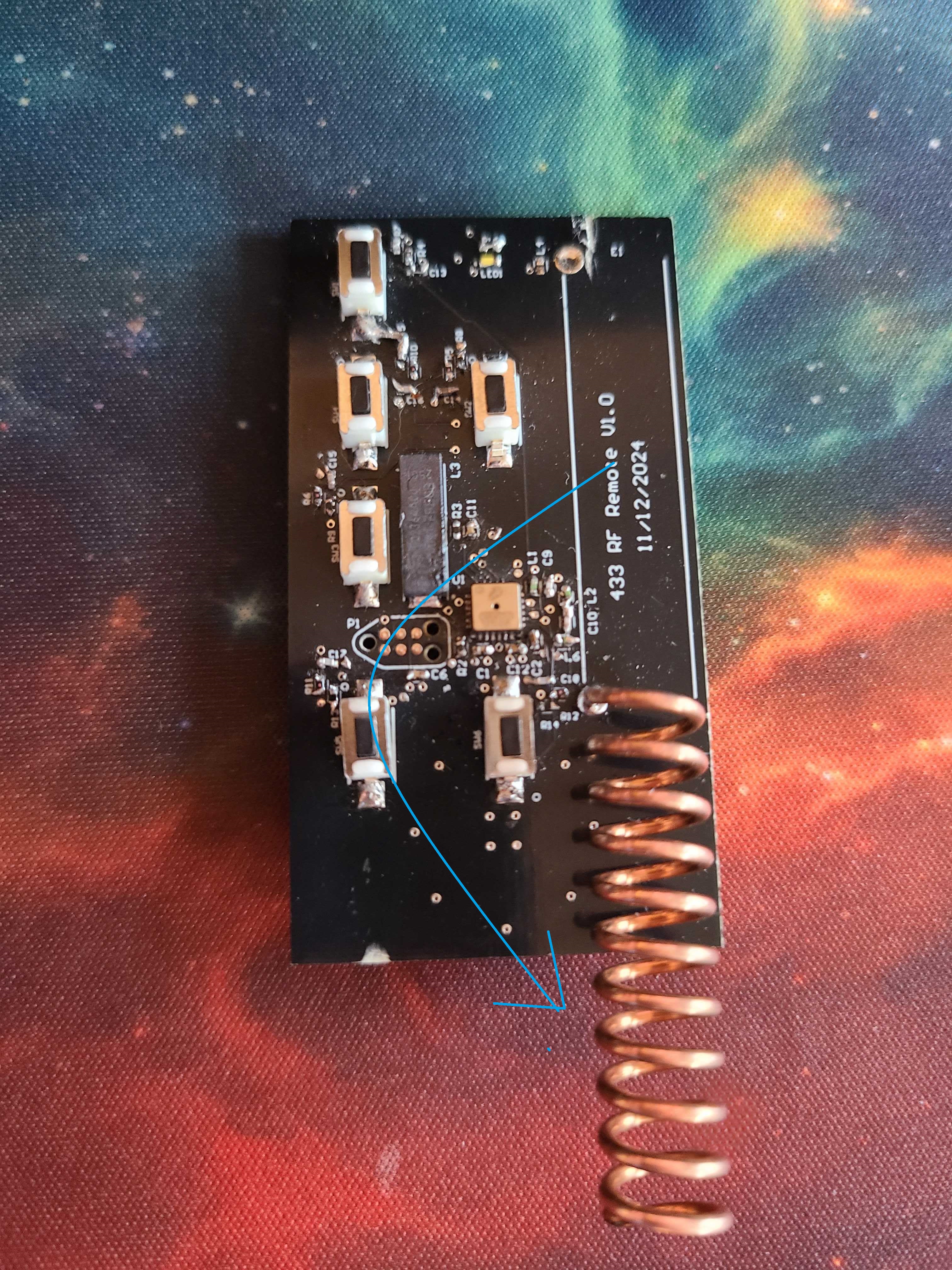
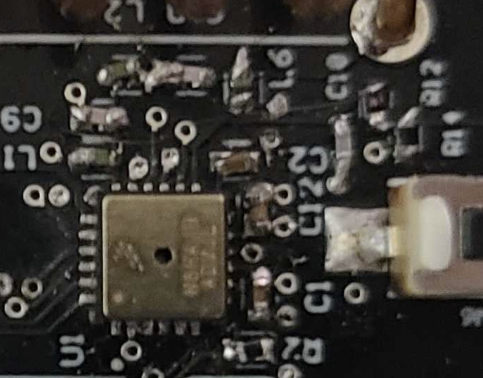
RF Debugging & Fixes
The first revision taught me a lot about RF layout. Moving the antenna away from ground and power planes, improving solder joints, and cleaning up the layout dramatically improved range and reliability.
RF Lessons Learned
- Antenna over continuous planes can hurt range and detune the coil.
- Lead dress and connector geometry matter more than they look at 433 MHz.
- Consistent solder reflow equals more consistent RF behavior across builds.
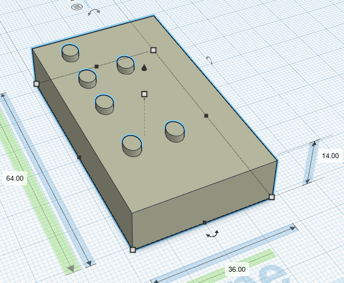
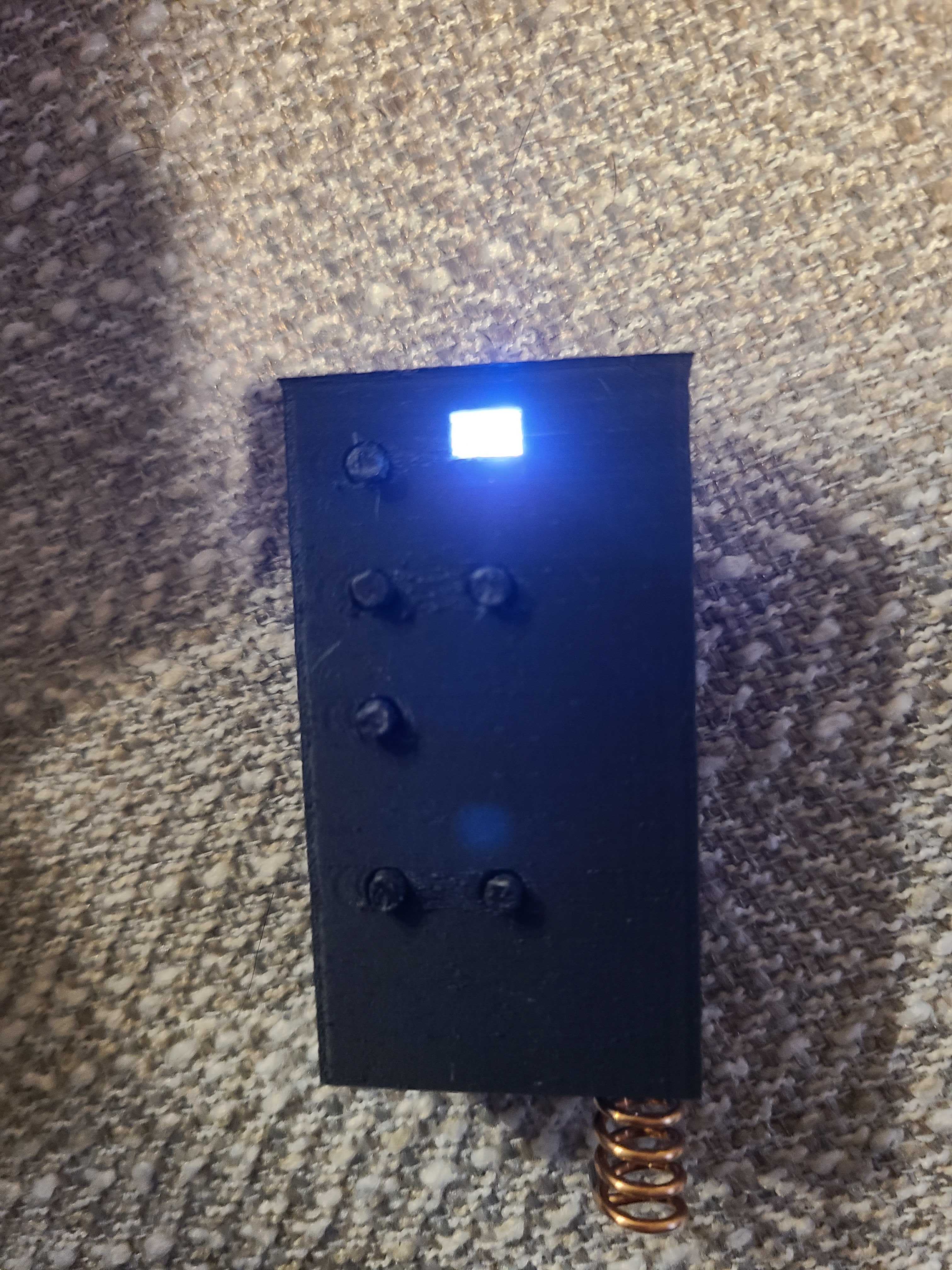
Rectangular Remote Case
The first case version was a classic rectangular remote: easy to print, easy to hold, and a good playground for button spacing and board retention features.
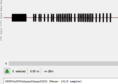
TouchTunes RF Remote
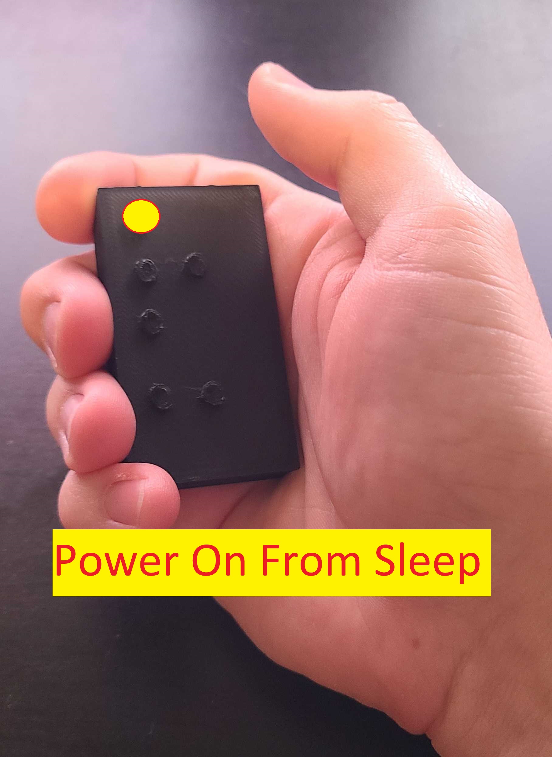
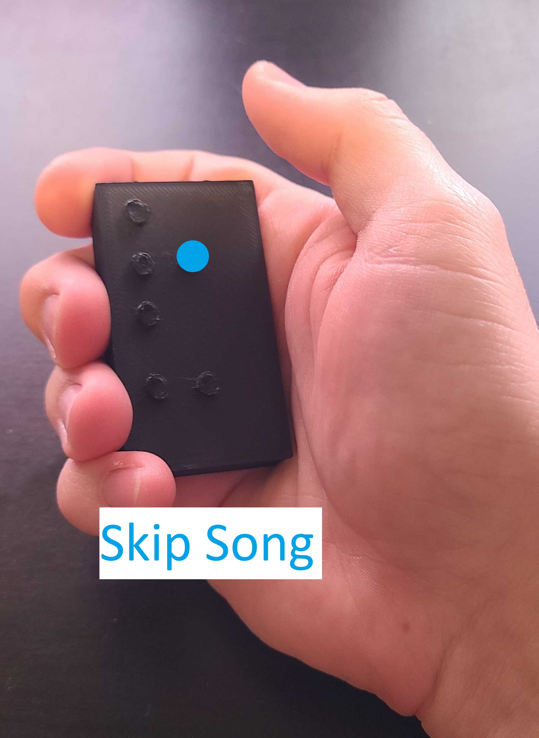
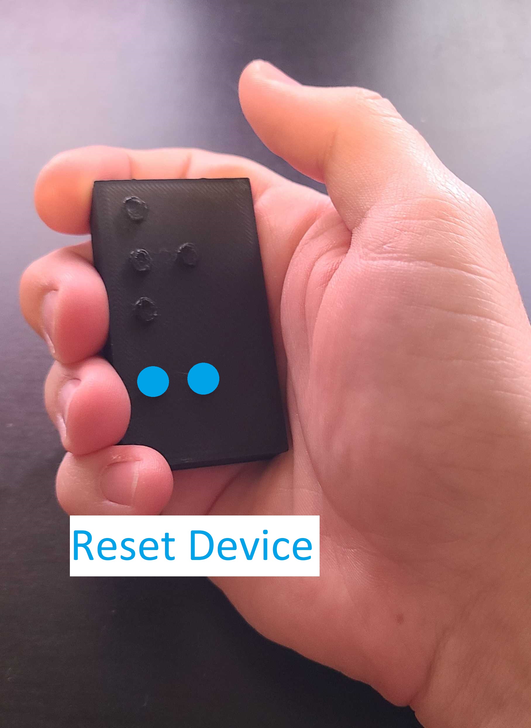
To give the remote a real job, I decoded the RF protocol used by TouchTunes jukebox remotes and mapped the buttons to volume control, play/pause, skip, and pin programming. The remote wakes from sleep on the first button press, then returns to sleep automatically after a timeout.
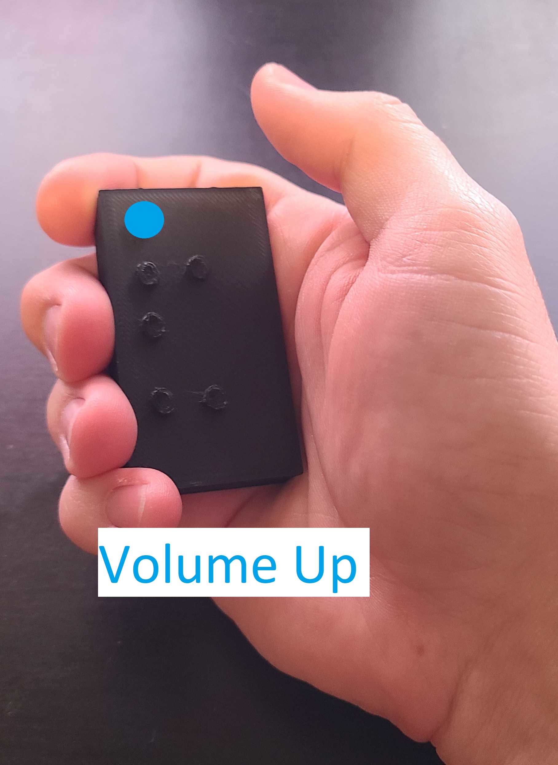
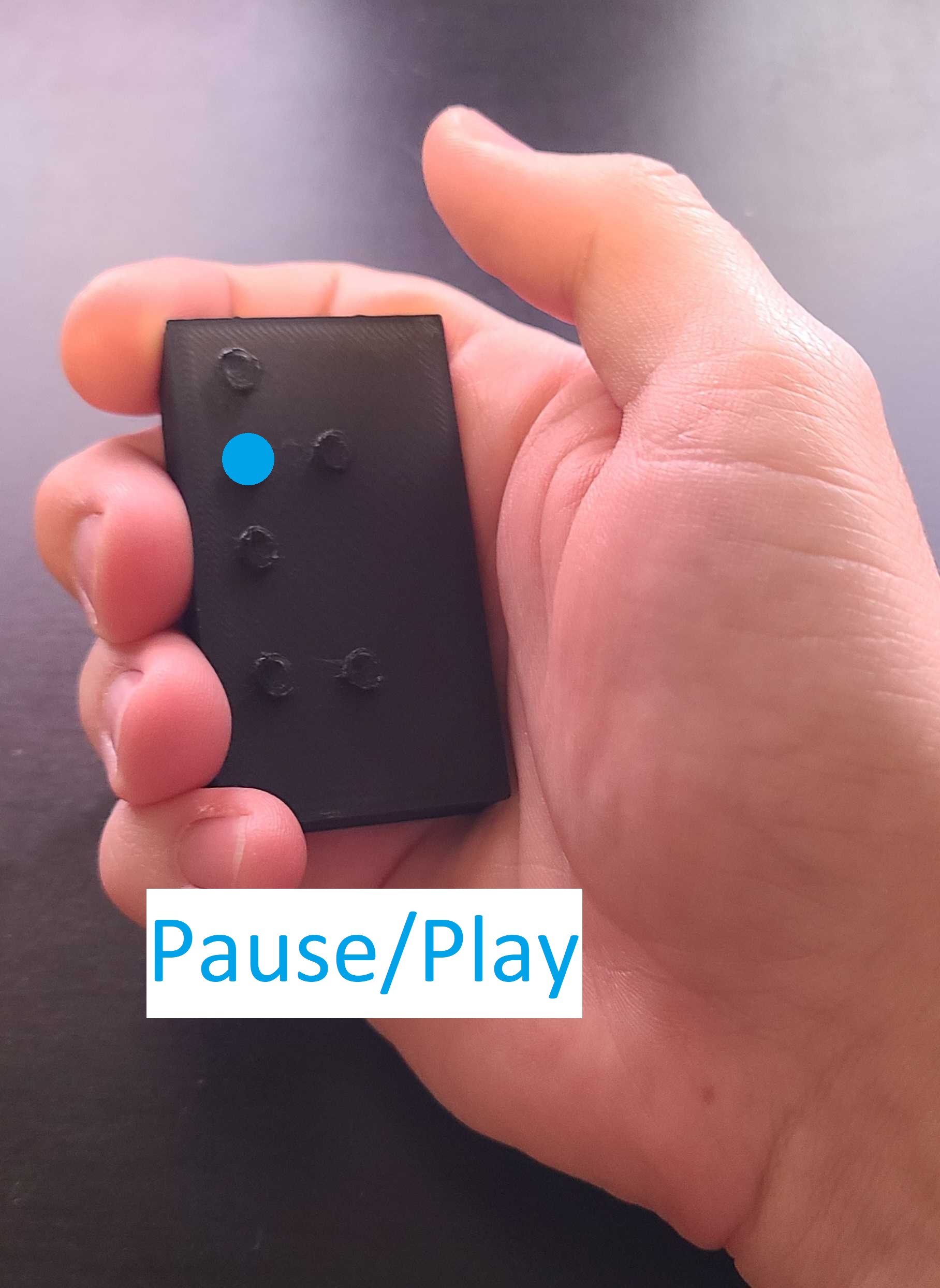
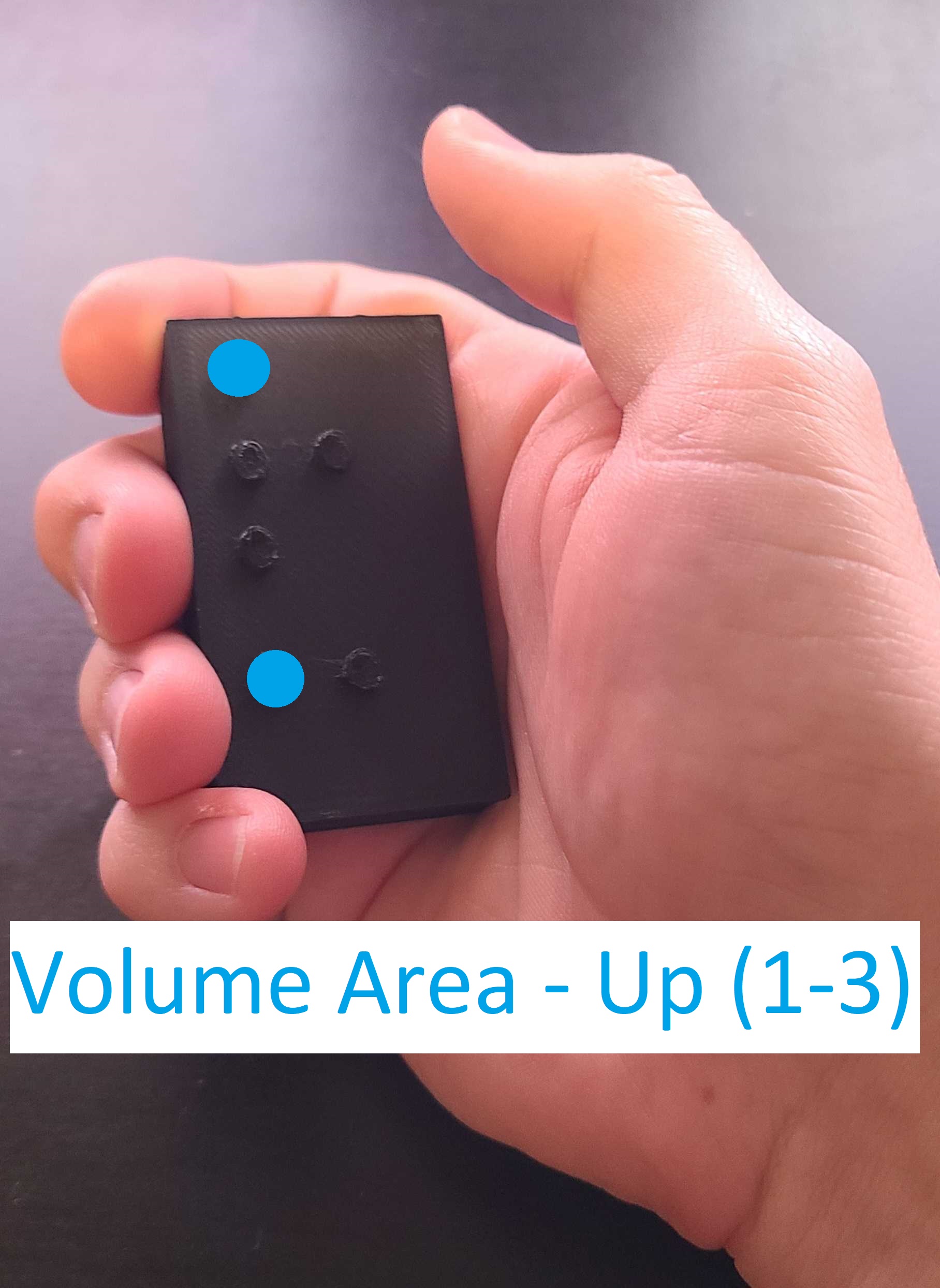
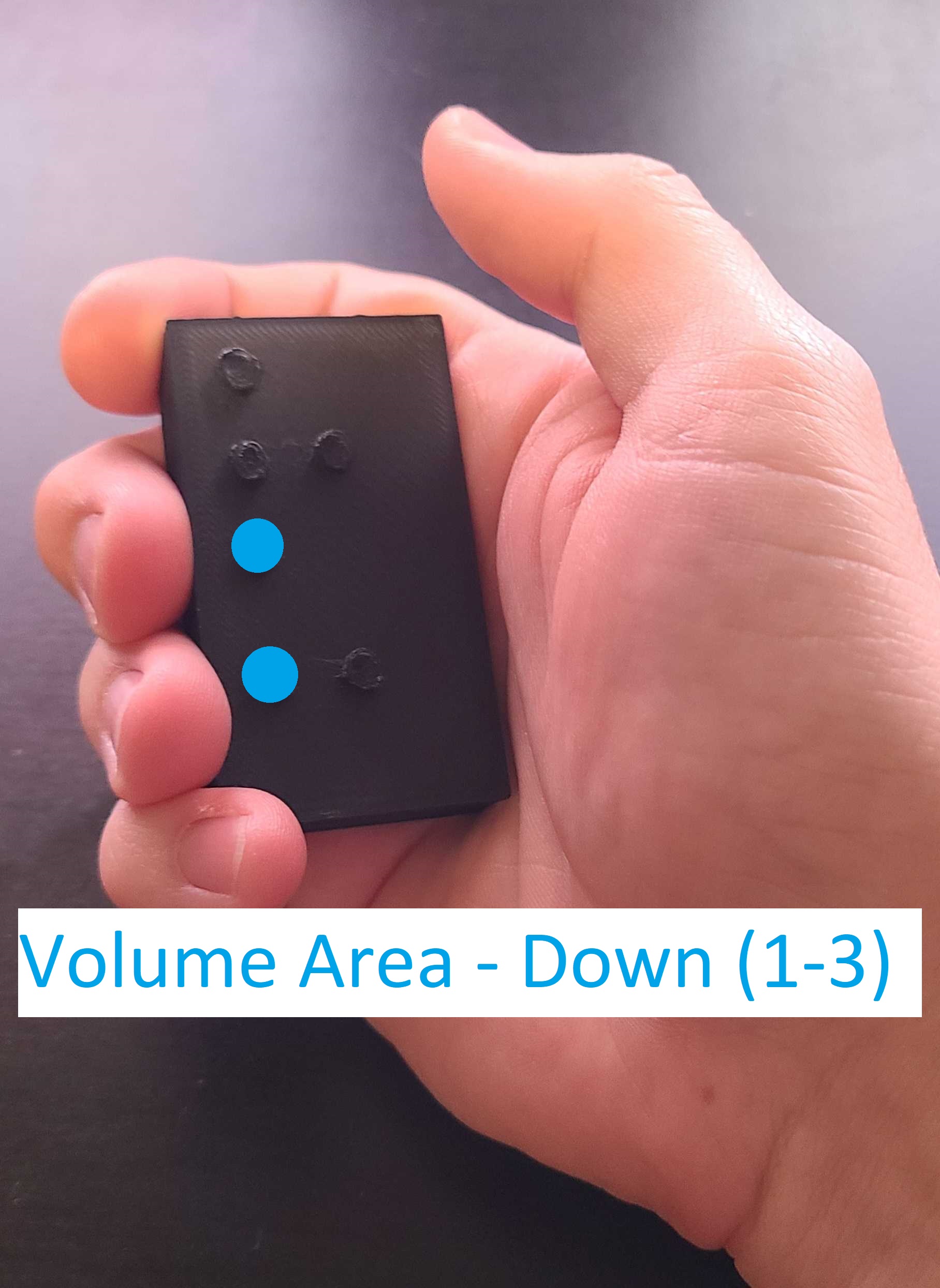
When you select change your volume area, the LED will flash out which area is newly selected.
There are 256 different pins. Each juke box can have a different pin. Once you find your pin, the Volume Up, Volume Down, Pause/Play, and Skip song will use your selected pin. This sends a volume up signal with every chagne of the pin so that the user of the remote can verify when they have the correct pin. Most Touch Tunes work on Pin 0.
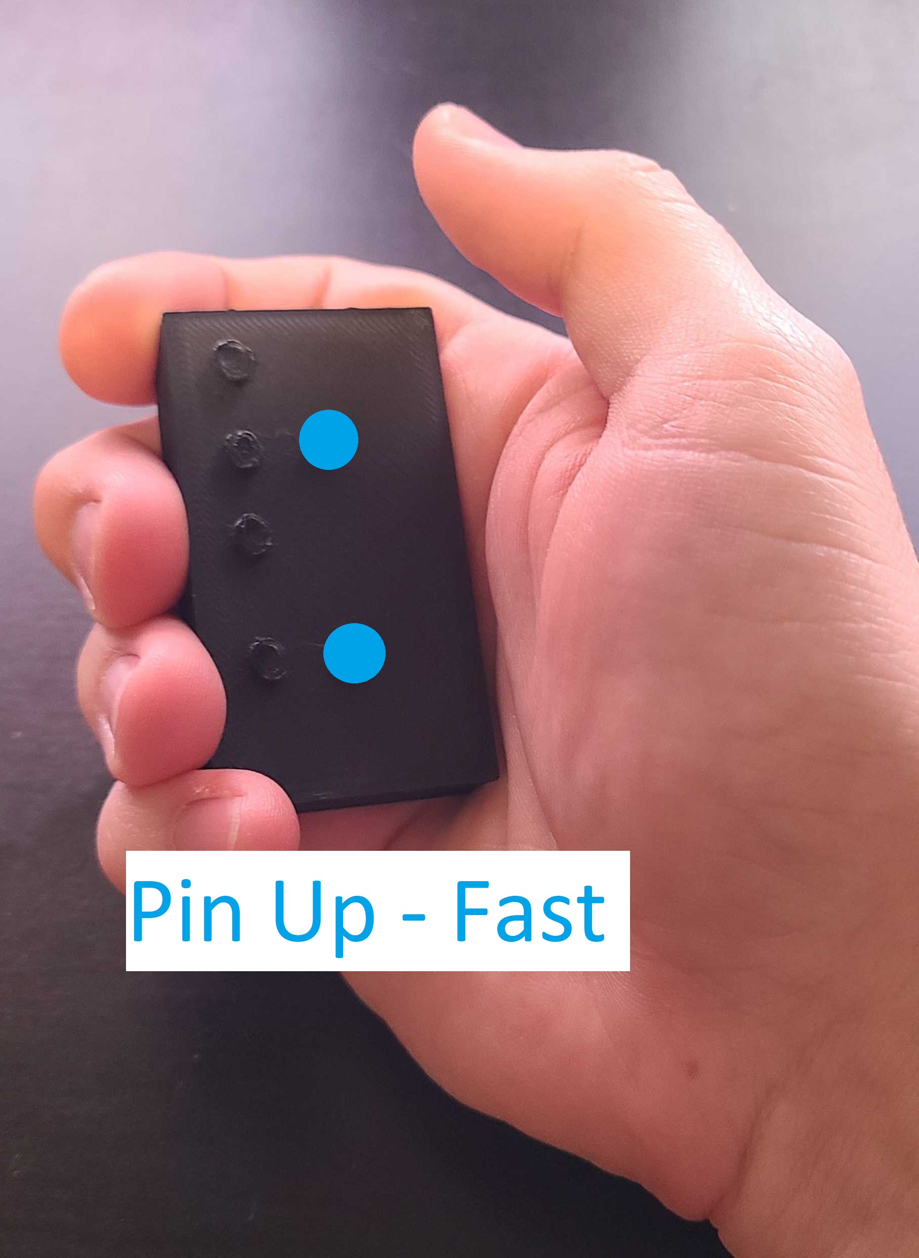
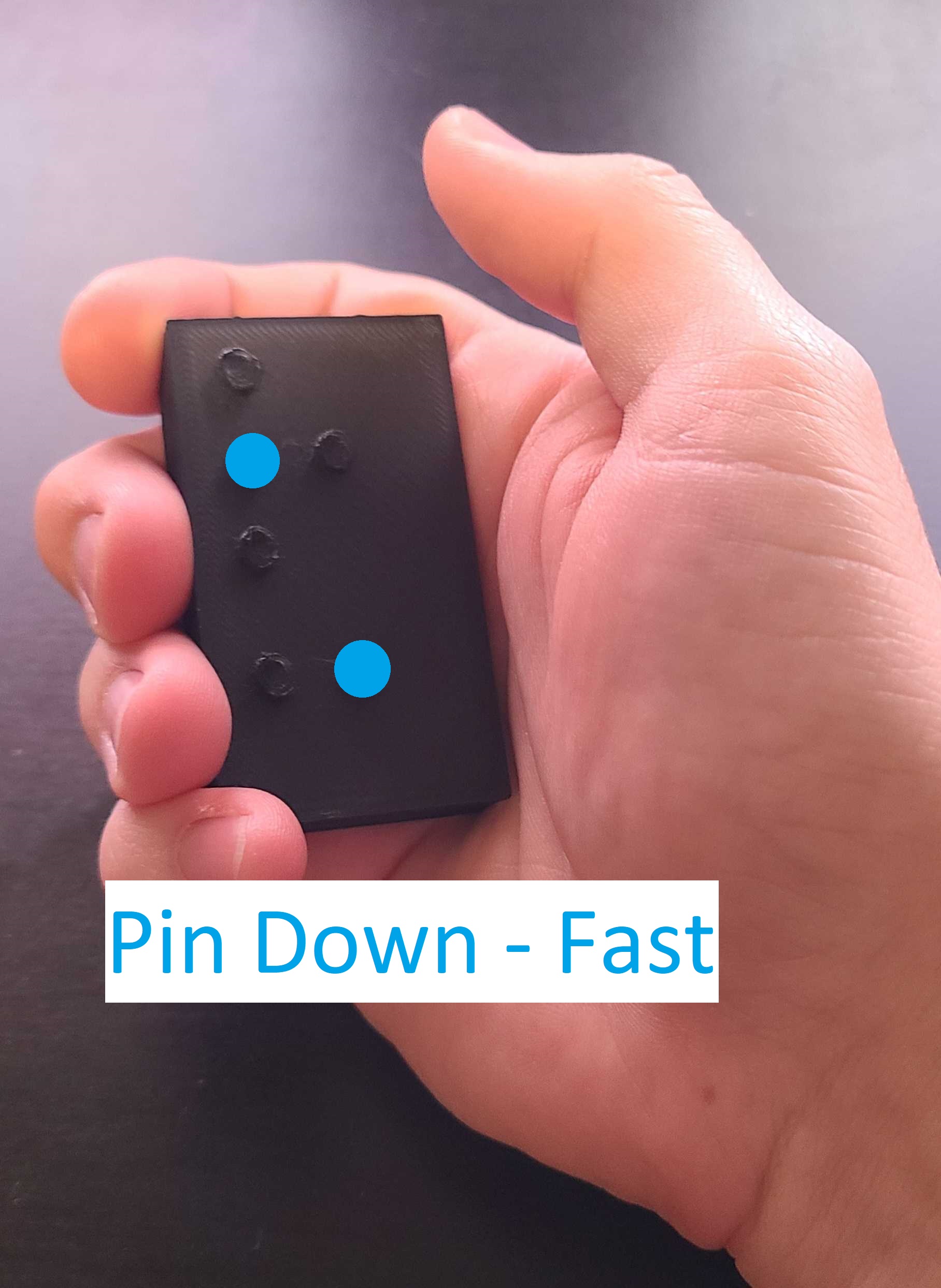
How to find the pin of your juke box: Starting at Pin 0, cycle up pins using Pin Up - Fast. Once you pass a pin that interacts with your juke box, you can go back over that pin with Pin Up/Down - Slow to set your remote to the correct Pin.
TouchTunes Behavior
- Remote must be woken from sleep before use; auto-sleeps ~10 seconds after last press.
- Volume Up/Down, Pause/Play, and Skip all respect the currently selected pin and area.
- There are 256 possible pins; most TouchTunes units default to Pin 0, but the remote can scan quickly using Pin Up/Down – Fast, then refine using slower steps.
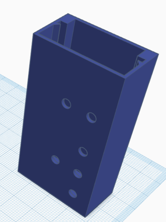
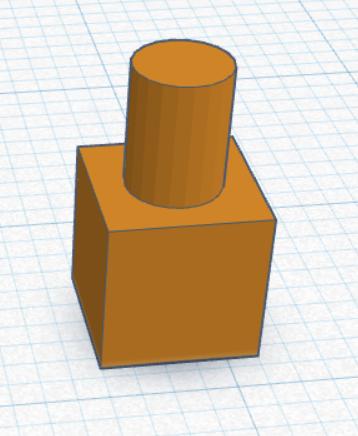
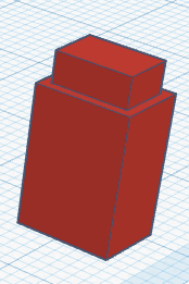
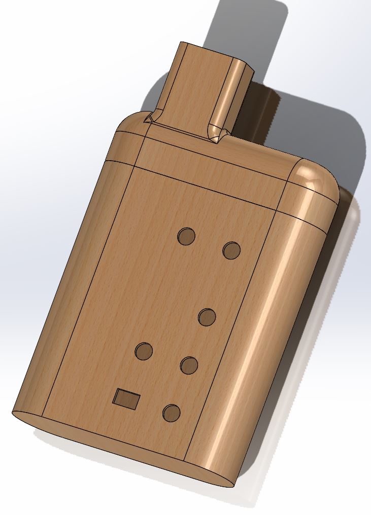
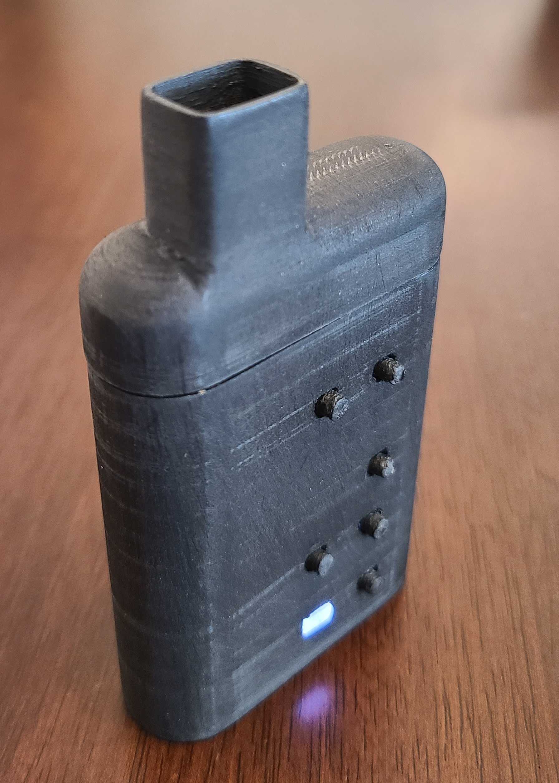
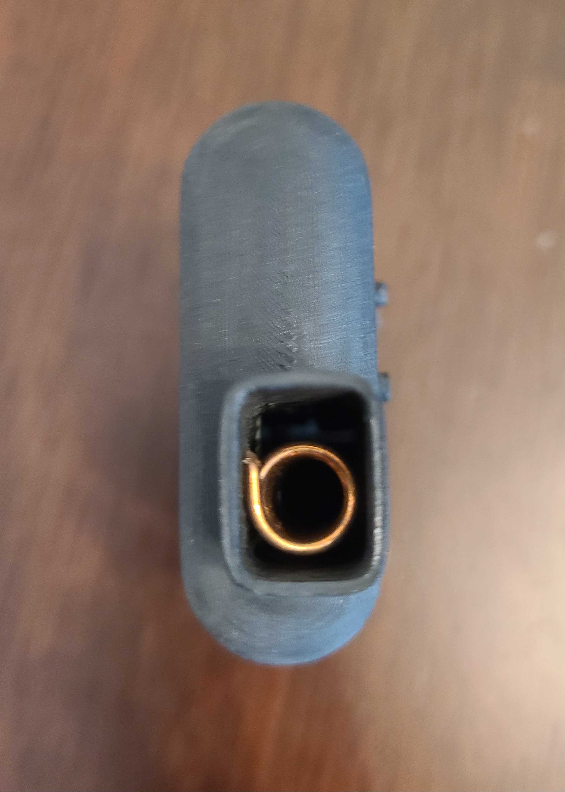
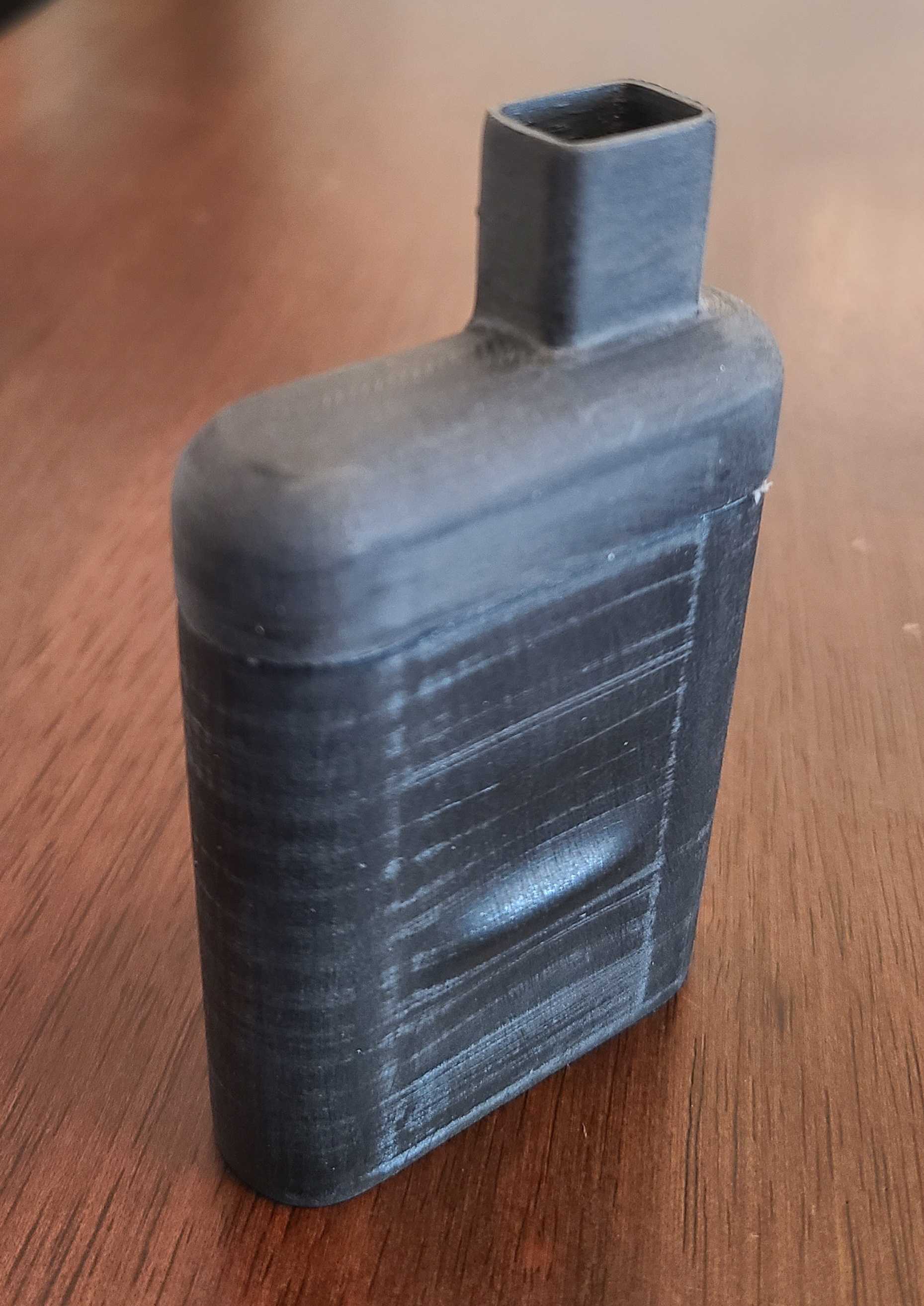
Incognito “Vape” Case
While testing the TouchTunes remote at a bar, the idea came up to disguise it as a vape. A couple of days of SolidWorks tutorials later, I had a vape-style case that fit the remote perfectly – and fooled a few friends who thought I’d picked up vaping.

Status
The remote works reliably as a TouchTunes controller and as a general-purpose 433 MHz platform. The rectangular and vape-style cases both hold the board securely and feel good in hand, making this a solid base for future handheld RF projects.