Timing Budget Check
Before committing, I verified the LPC5536 microcontroller could comfortably keep up with the incoming PWM while also generating a new one.
Turning the “meh” ventilated seats in my 2023 RAV4 into actually-cold seats by reverse-engineering the OEM PWM control and inserting an LPC5536-based controller in-line with the blower signal.
The RAV4’s ventilated seats only run the fan at full speed when the HVAC fan is on high and blowing out the top vents. I wanted the seat to blast at “max chill” whenever I asked for it – independent of the cabin fan – without breaking any OEM features.
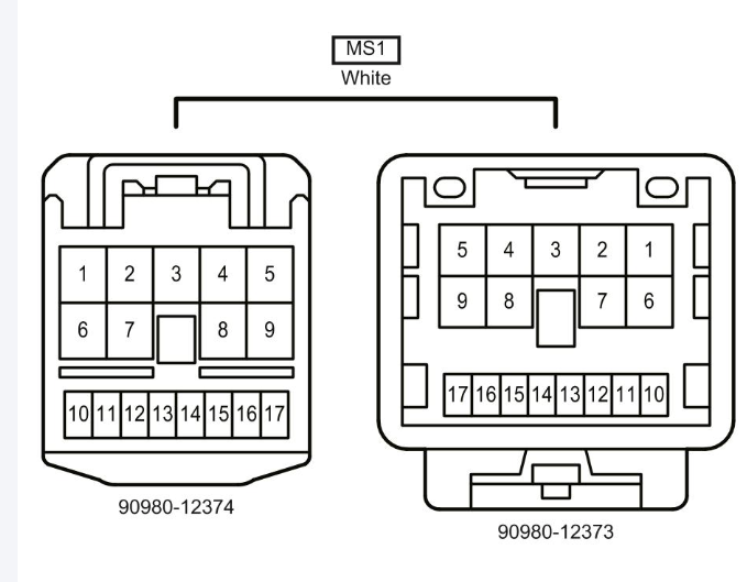
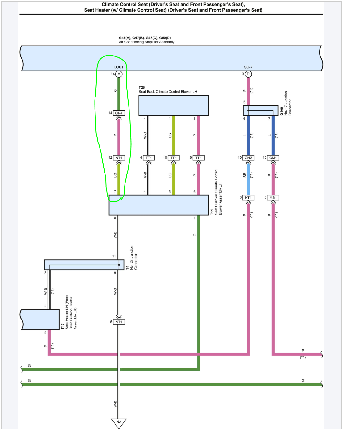
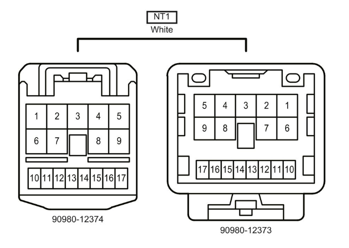
I started with the Toyota wiring diagrams to locate the seat climate control connectors, power feeds, and the mysterious control line that changes with the ventilated seat levels.

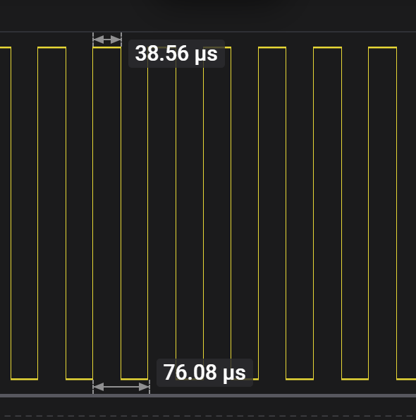
With the wiring identified, I tapped into the control line and used a Saleae logic analyzer to see what the seat controller was actually doing.

At the seat’s three levels (with normal HVAC settings), the duty cycle looked like:
When the cabin HVAC fan was on max and pointed at the head, the same “High” seat setting jumped up to about 53% duty cycle.


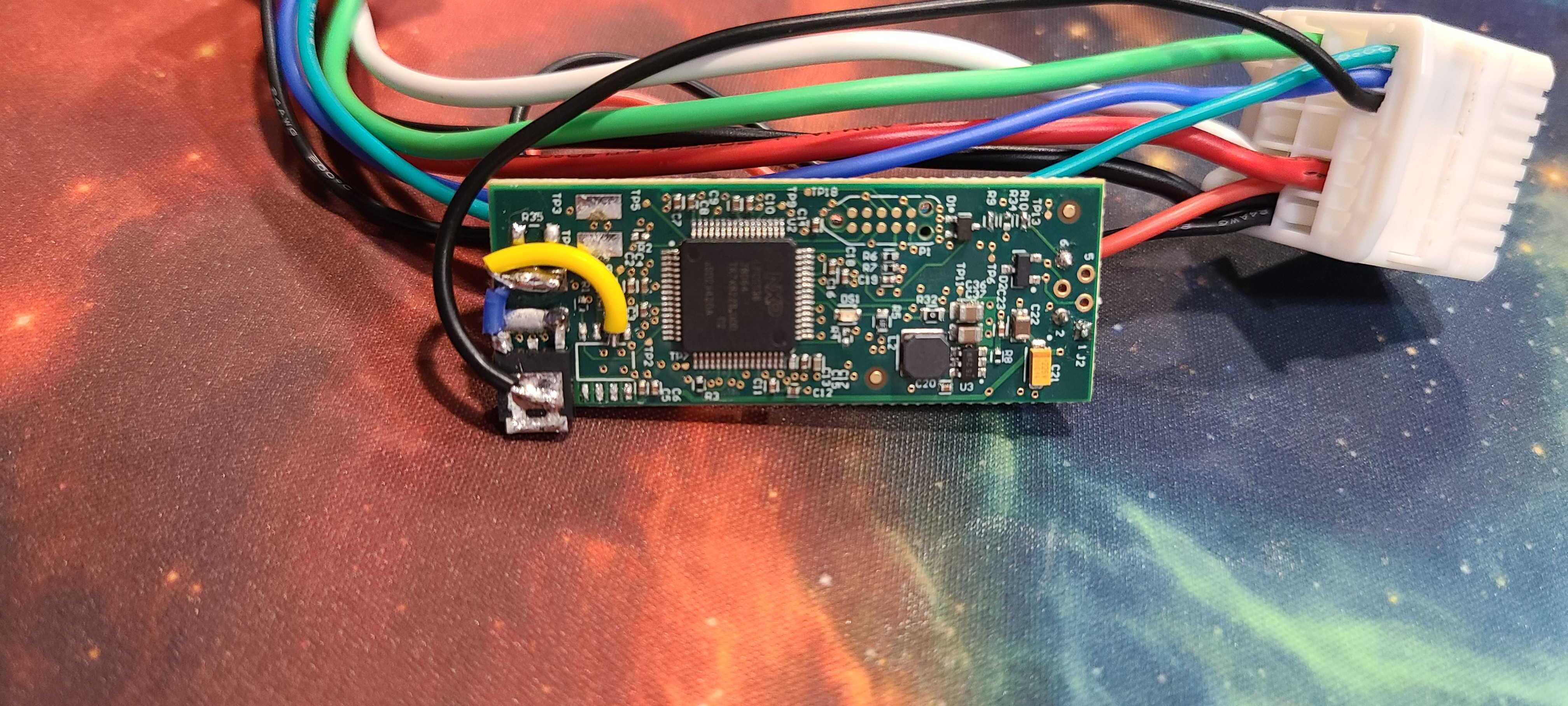
I first proved this out on an Adafruit board, then migrated everything to an LPC5536-based board I’d previously designed. The module sits inline between the OEM controller and the seat blower.
Before committing, I verified the LPC5536 microcontroller could comfortably keep up with the incoming PWM while also generating a new one.
I repurposed an LPC5536 board, adding a MOSFET on a PWM pin to sink the blower ground. The OEM control line feeds an input with an internal pull-up so the firmware can read the PWM while still emulating the OEM load.
If the OEM ever tries to drive above 50% (e.g., head-blaster HVAC mode), the module just passes the original PWM through.
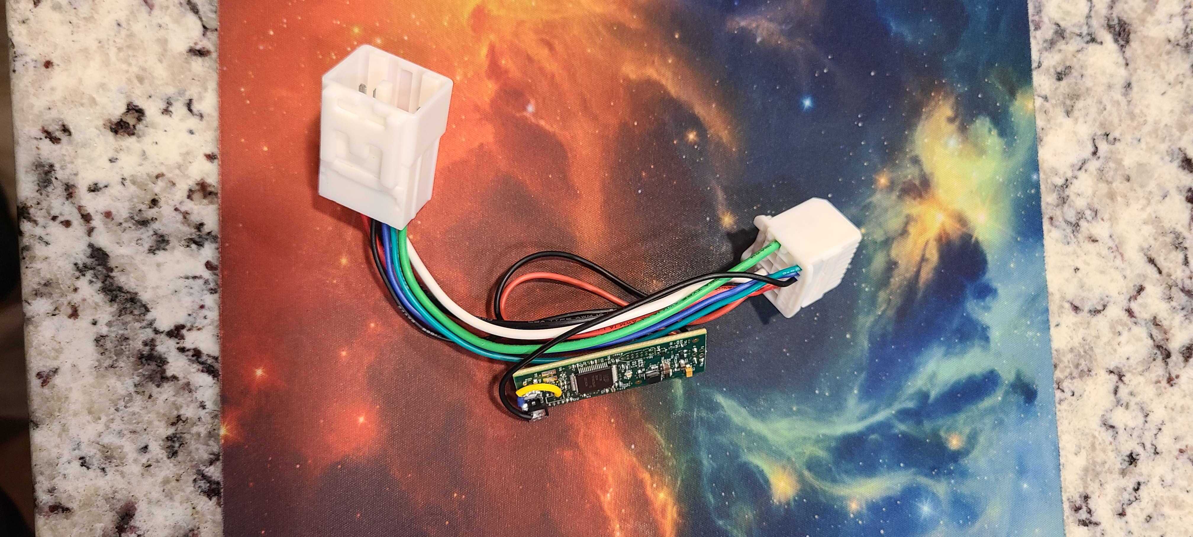
To keep things OEM-like, I designed a small enclosure and a plug-and-play harness that sits between the factory seat connector and the car harness – no wires cut.


The module tucks under the driver’s seat and rides along with the factory harness. The seat still moves freely and everything remains serviceable.


To visualize the difference, I put a trash bag over the seat perforations and timed how long it took to suck the bag flat with and without the module installed.
That’s roughly a 30–40% reduction in time, which matches the duty-cycle changes and absolutely feels better on real drives.
The module has been working reliably in daily driving. The OEM controls still work exactly as before – I just get “the better version” of the ventilated seats without needing the HVAC blasting at my face.
Overall, the Cool A.F. Seats project was a fun mix of automotive wiring research, signal analysis, real-time firmware, man in the middle, and a little bit of comfort-focused over-engineering.