Project Background
After working on a farm for 2 years I noticed some areas for improvement. In the cow barns, the electric gates are run by 2 buttons that must be pressed and held to operate: one to run the gate forward down a ~150ft hallway and one to run the gate back the opposite direction. After watching the farmers jam a metal rod into the button to operate the gate for 3-4 minutes, forget about it, and burn out the $600 motor 3 times in two months, I took it upon myself to design an automated solution.
Circuit Design
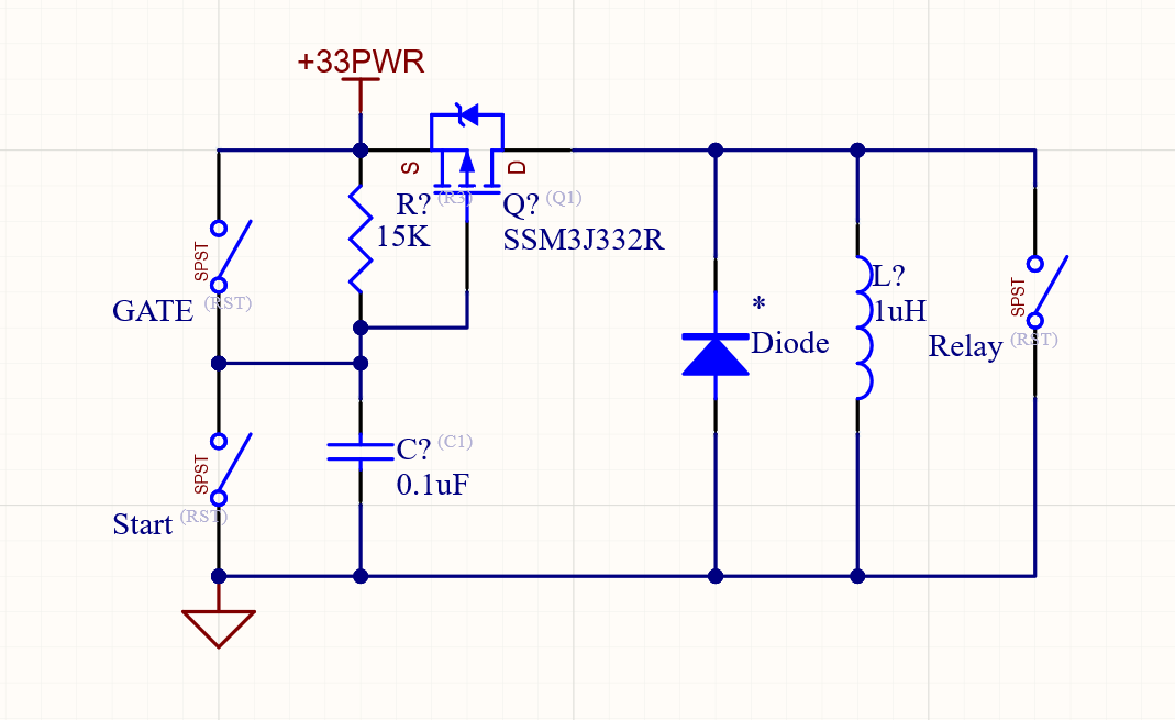
The goal of this project was to create a circuit that once activated would automate the process of supervising the gate as it rolled to one end of the hallway and shut it off automatically to alleviate user error. This circuit was designed around a mechanical relay that could drive the gate's 110 volt AC, 0.5 amperes controls. I used an RC discharge timer driving a mosfet to run the relay in the gate controller instead of a programmable circuit. This was designed to be used with Lithium AA batteries so that it could be run in extreme temperatures with minimal voltage drop. Along with better stability in extreme weather, lithium batteries also have a higher voltage compared to alkaline or NiMH batteries. This circuit will not keep the gate turned on for long periods of time with lower voltage batteries which helps protect it from burning out the motor when the gate reaches the end of its rail.
The circuit has a button to start the gate controller timer and one to end it. For extra protection, the circuit also has an auxiliary plug for ending the timer in case the gate makes it to the end of the rail. The auxiliary plug is made to have a magnetic contact switch hooked into it which would stop the timer when the gate is in proximity to the end of the rail.
Circuit revision/redesign done by Roman Robles PE Electrical Engineer
Testing Circuit
I tested the circuit to make sure that the math of the relay would drive the gate the full length of the hallway and ensure that the RC Discharge Timer math was correct to prevent motor burnout.
Box Design
I designed and 3D printed a case with fastener holes for the covers and separate covers to access the batteries and circuit. This case is meant to protect both the user from the electronics as well as prevent mishandling and tampering of the electronics from both humans and cows that pass by, I wouldn't want any beef with a cow taking a hoof at engineering.
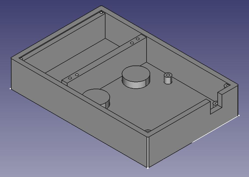
Cad Design
3D Printing the box
Finished Box