The Atari 7800 Diagnostic Cartridge Page
Important Note
This page was written in order to:
- Document the results of this investigation
- Share the results of this investigation with the general public
All ROMs posted on this page are for learning purposes only. Downloading any ROMs from
this page assumes that you own the Atari 7800 Diagnostic Cartridge yourself.
Also, I am not responsible for any harm that these files cause to:
- your computer
- your house
- your livestock
- your brain
- your life
Your fate is in your own hands-- download and use at your own risk. :)
Foreward
Ever since the Digital Press Guide first came out, I knew that I wanted a 7800 diagnostic
cart. Come on! It was a rarity 6! Soon I found myself about $25 poorer, but with that
diagnostic cart which I so badly wanted. Why would I want such a crappy old cart, you ask?
Simple-- it was an enigma that needed to be figured out. But I'm getting ahead of myself.
So, let's begin. What does this thing look like?
 Ok, so we plug it in, and what happens?
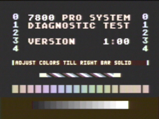
Well, first you get a screen like this:
Ok, so we plug it in, and what happens?
Well, first you get a screen like this:
 Then, hit any key, and you'll more than likely get:
- A blank screen
- A "Yuk face" screen that displays error code 06
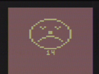 The famous "Yuk face" screen
Sometimes, other codes are presented.
It was at this point that I thought, "Boy, what's really going on here?"
I started out with some research via the web.
http://www.atari7800.org/labelscans/Diagnostic.htm
http://www.atari7800.org/screenshots/Testscreen.htm
http://www.atari7800.org/manuals/Diagnostic.htm
These pages are a great start by a friend of mine, Mitch. He's been very faithful to the
Atari 7800 community in his efforts, which I applaud. I got more motivated at this point--
There had to be more info available than just what was listed on this site.
So, I did some experimentation. I went to a friend's house, and we decided to try to
power cycle the cartridge "a lot", and try to document any statistical patterns that
we could find. We found nothing conclusive at first.
(Note that that's the kind of friend that I am-- I may one day show up at your door
with an Atari cartridge in hand and expect you to be interested in helping me to
debug its software for 2 straight hours... but that's kinda off topic).
We began to do some tests with the Joystick Ports. If you plug a controller into
either port and wiggle the stick or press a button, you get a rewarding behavior of--
nothing.
All had seemed lost until we tried putting a keypad controller into the port. And
presto! Error code 6 immediately. We didn't have paddles on us at the time, but
if memory serves, they should yield the same result. A neat experiment is to let
the screen go "black", and then plug the keypad controller into the left joystick
port. You'll notice that once the pins are touching, error code 6 appears. This
is true even if you wait for 30 minutes on the black screen before plugging in the
keypad controller.
This got me thinking-- the 7800 must want to communicate with "something" using the
controller ports. I mean, it was in a paused state, and waiting for input. But, what?
"Something" must have been specifically developed to go with that cartridge, and plug
into either one or both of the joystick ports.
Instantly, I called up Best Electronics and ordered a pair of their
diagnostic plugs (part number MA017602). When they arrived, I plugged them in... and...
dammit! They still gave me an error code 06. Oh, how I loathed the "Yuk face".
I called up Best Electronics again to see if they knew of
any special diagnostic plugs that were supposed to go specifically with the Atari 7800
diagnostic cartridge. Alas, it was not meant to be. Since no documentation of error
codes was ever made available to Best Electronics, there certainly
was little chance that the correct diagnostic plugs would ever fall into public hands.
So, I started from scratch, and did my first disassembly work.
I first learned that the "Yuk face" screen is all done with 2600 graphics. I realized
this when I looked at the first section of code that I disassembled. It is also easy
enough to see by doing the following experiment:
I used "Frhed", a free hex editor (You can find it on the web) to do this.
Try taking your diagnostic cartridge ROM, removing the first 128-byte header
(if you're using a .a78 file), and then remove the lower 12K of the cartridge.
You would end up with a 4K ROM image. It will look like this file.
Try running this binary on an Atari 2600 emulator. You'll most likely see the screen with the
Yuk face come up, with error code 03. The first thing that the cart does is do a store to address
$2000, and then reads it back. The Atari 7800 has RAM in this section, so reading it back and
comparing it to the stored value should wourk great. In 2600 mode, it's not the case. The check
will fail, and dump you into the code that displays the "Yuk face" with error code 03.
Some more hacking (and 2600-based disassembly) of that 4K file showed me that there was one more
exciting 2600-configuration screen in the cartridge. To see, it, take your 4K ROM image,
and change the data at the start vector ($FFFC and $FFFD) with a hex editor.
Old data (Startup vector = $F000):
$FFFC: $00
$FFFD: $F0
New data (Startup vector = $F194):
$FFFC: $94
$FFFD: $F1
A binary ROM image with this configuration can be downloaded here.
Low and behold, a screenshot like this will appear after booting the ROM on a
2600 emulator:
The famous "Yuk face" screen
Sometimes, other codes are presented.
It was at this point that I thought, "Boy, what's really going on here?"
I started out with some research via the web.
http://www.atari7800.org/labelscans/Diagnostic.htm
http://www.atari7800.org/screenshots/Testscreen.htm
http://www.atari7800.org/manuals/Diagnostic.htm
These pages are a great start by a friend of mine, Mitch. He's been very faithful to the
Atari 7800 community in his efforts, which I applaud. I got more motivated at this point--
There had to be more info available than just what was listed on this site.
So, I did some experimentation. I went to a friend's house, and we decided to try to
power cycle the cartridge "a lot", and try to document any statistical patterns that
we could find. We found nothing conclusive at first.
(Note that that's the kind of friend that I am-- I may one day show up at your door
with an Atari cartridge in hand and expect you to be interested in helping me to
debug its software for 2 straight hours... but that's kinda off topic).
We began to do some tests with the Joystick Ports. If you plug a controller into
either port and wiggle the stick or press a button, you get a rewarding behavior of--
nothing.
All had seemed lost until we tried putting a keypad controller into the port. And
presto! Error code 6 immediately. We didn't have paddles on us at the time, but
if memory serves, they should yield the same result. A neat experiment is to let
the screen go "black", and then plug the keypad controller into the left joystick
port. You'll notice that once the pins are touching, error code 6 appears. This
is true even if you wait for 30 minutes on the black screen before plugging in the
keypad controller.
This got me thinking-- the 7800 must want to communicate with "something" using the
controller ports. I mean, it was in a paused state, and waiting for input. But, what?
"Something" must have been specifically developed to go with that cartridge, and plug
into either one or both of the joystick ports.
Instantly, I called up Best Electronics and ordered a pair of their
diagnostic plugs (part number MA017602). When they arrived, I plugged them in... and...
dammit! They still gave me an error code 06. Oh, how I loathed the "Yuk face".
I called up Best Electronics again to see if they knew of
any special diagnostic plugs that were supposed to go specifically with the Atari 7800
diagnostic cartridge. Alas, it was not meant to be. Since no documentation of error
codes was ever made available to Best Electronics, there certainly
was little chance that the correct diagnostic plugs would ever fall into public hands.
So, I started from scratch, and did my first disassembly work.
I first learned that the "Yuk face" screen is all done with 2600 graphics. I realized
this when I looked at the first section of code that I disassembled. It is also easy
enough to see by doing the following experiment:
I used "Frhed", a free hex editor (You can find it on the web) to do this.
Try taking your diagnostic cartridge ROM, removing the first 128-byte header
(if you're using a .a78 file), and then remove the lower 12K of the cartridge.
You would end up with a 4K ROM image. It will look like this file.
Try running this binary on an Atari 2600 emulator. You'll most likely see the screen with the
Yuk face come up, with error code 03. The first thing that the cart does is do a store to address
$2000, and then reads it back. The Atari 7800 has RAM in this section, so reading it back and
comparing it to the stored value should wourk great. In 2600 mode, it's not the case. The check
will fail, and dump you into the code that displays the "Yuk face" with error code 03.
Some more hacking (and 2600-based disassembly) of that 4K file showed me that there was one more
exciting 2600-configuration screen in the cartridge. To see, it, take your 4K ROM image,
and change the data at the start vector ($FFFC and $FFFD) with a hex editor.
Old data (Startup vector = $F000):
$FFFC: $00
$FFFD: $F0
New data (Startup vector = $F194):
$FFFC: $94
$FFFD: $F1
A binary ROM image with this configuration can be downloaded here.
Low and behold, a screenshot like this will appear after booting the ROM on a
2600 emulator:
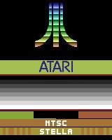 YES!!!
So, there is indeed a hidden screen. I nearly soiled myself when I realized what I was seeing.
This screen had not been seen by anyone for at least the past 10 years. No one knew it was here.
I was unbelieveably excited, but I had to know more. How could I unlock this screen without
simply hacking the software? There had to be a way!
Well, the rest of the story is kind of boring to the real world. It involved lots of careful
disassembly of the code, which made me figure out what hardware was required to make
everything work.
So, without futher adieu, here it is-- the magic "hardware":
YES!!!
So, there is indeed a hidden screen. I nearly soiled myself when I realized what I was seeing.
This screen had not been seen by anyone for at least the past 10 years. No one knew it was here.
I was unbelieveably excited, but I had to know more. How could I unlock this screen without
simply hacking the software? There had to be a way!
Well, the rest of the story is kind of boring to the real world. It involved lots of careful
disassembly of the code, which made me figure out what hardware was required to make
everything work.
So, without futher adieu, here it is-- the magic "hardware":
 The magic hardware
Important notes:
The magic hardware
Important notes:
- Exactly 2 of these are needed-- one in each port.
- To validate pins 7 and 8, you can tie a wire from pin 7 to a resistor to an LED to pin 8.
One other thing to note is that the resistor that I used was 47 k-ohms. There is some variablility
allowed, but I never calculated upper and lower thresholds. 47 k-ohms was a middle value. I think
that 15 k-ohms to 70 k-ohms would be sufficient (if I remember correctly). Anyway, uou can get a
bundle pack of 47 k-ohm resistors at radio shack for about $3. The part number was 271-1342 for a
pack of 5 (47K-ohms resistance, 1/4 watt, 5% tolerance).

Error codes

While disassembling the code, I found some of the error codes.
Note that the error code is sent to the "Yuk face" routine as a hex code on the Y-register, which
is then translated.  $0 thru $9 translate to 0 thru 9, and $A translates to "X".

Here is the list that I've accumulated:

01 - Failure to debounce either the reset switch or select switch
02 - RAM $0480 - $04FF error
03 - Diagnostic cart is running on a 2600 (cannot store to $2000)
04 - Status flags or stack error
05 - Failure of a PIA Timer
06 - Control port failure; occurs if not using proper diagnostic plugs or if the SWCHA ports are
     broken
07 - INPT failure; occurs if not using proper diagnostic plugs or if there is a failure in one of
     the INPT registers on the PIA
08 - diagnostic plug failure (if I remember right, this has to do with not having the 47 k-ohm
     resistors on the plugs.  I will re-investigate later.
11 - RAM $0140 - $01FF error
12 - RAM $0040 - $00FF error
14 - $FFF9 error-- Either the left nibble at $FFF9 does not contain a valid bank size (i.e. > 48K)
     or the right nibble isn't 7.

Error codes in the code that I haven't figured out (yet):

1) Numeric codes:
X0, X1, X2, X3, and X4 -- I found these codes in the following code segment:

;;;;;;;;; START CODE ;;;;;;;;;;;;;;;;;;

LF884:
     LDA    $F88B,Y  ; $B9,$8B,$F8
     TAY             ; $A8
     JMP    $F026

LF88B: ; SIX error codes used by F884.
     dc.b   $A4      ; will display "X4"
     dc.b   $A1      ; will display "X1
     dc.b   $A2      ; will display "X2
     dc.b   $A0      ; will display "X0
     dc.b   $A3      ; will display "X3
     dc.b   $03      ; will display "03

;;;;;;;;;;; END CODE ;;;;;;;;;;;;;;;;;;


Note that there are also other errors that are not caught with an "error code".  For example,
on the first screen where it says "7800 PRO SYSTEM DIAGNOSTIC TEST VERSION    1:00",
you can also somehow trigger text that says "       BAD!!!!!".
This is found at $EB87, the third chunk of character map data, to be stored at $191E.
Disassembly info
The Diagnostic Cart ROM is broken into the following segments:

 128 bytes = header
8192 bytes = graphics data (not much)
8192 bytes = code

The second block of 8192 bytes can roughly be broken into 2 sections:
Section 1: 4096 bytes (mostly Atari 7800 code)
Section 2: 4096 bytes (mostly Atari 2600 code)

Let's look at this in more detail.

Section 1: Header

  This isn't too interesting.  This is for emulation purposes.

Section 2: Graphics data

  In my boredom, I painstakingly converted this 8K chunk into graphical representations.
  This way, you can see where some of the graphics not found in the actual sorce code exist.

  Using Mode 0: Monochrome

  Click here to see.  It's really too long for a standard web page.

  Using Mode 1: 160x2 4-color


  Using Mode 2: 320B 4-color


  Using Mode 3: 160x4 12-color


Section 3: Code data

  Note that these disassemblies are not complete at this time.  I work on them from time to time.
  For example, the "Error code 8" section in the second 4K disassembly file was traced out on
  line-paper a couple of months ago, but the comments have not yet made it into this disassembly
  file.  Hopefully, I'll get some time and motivation to make updates periodically.

  The first 4K (7800-based code) can be found here.

  The second 4K (2600-based code) can be found here.

The most exciting piece of code in my opinion is this:

	;************************
        ;* Subroutine:	        *
        ;*     WaitVBOn:        *
        ;************************
LE723: BIT    MSTAT   ;3   If in 2600 mode, this is BIT INPT0 (a shadow of INPT0!)
       BPL    LE723   ;2   This causes an infinite loop until the cap in the 2600 is charged.
              RTS     ;6

The reason that I had so much trouble finding out where that infinite-loop that was dependent
on the diagnostic plugs resided was because the code has completely different meanings if it
is run in Atari 2600 mode vs. 7800 mode (because the equate $28 translates to MSTAT in 7800 mode,
but it translates to a shadow equate for INPT0 in 2600 mode.  This is the first and only example
I've ever seen of dichotomous code which is used both ways.   The 2600-mode based access occurs
at line $F9A9.  All other accesses are 7800-based accesses.  Isn't it awesome!?!?
Section 3: Code data
Note that these disassemblies are not complete at this time. I work on them from time to time.
For example, the "Error code 8" section in the second 4K disassembly file was traced out on
line-paper a couple of months ago, but the comments have not yet made it into this disassembly
file. Hopefully, I'll get some time and motivation to make updates periodically.
The first 4K (7800-based code) can be found here.
The second 4K (2600-based code) can be found here.
The most exciting piece of code in my opinion is this:
;************************
;* Subroutine: *
;* WaitVBOn: *
;************************
LE723: BIT MSTAT ;3 If in 2600 mode, this is BIT INPT0 (a shadow of INPT0!)
BPL LE723 ;2 This causes an infinite loop until the cap in the 2600 is charged.
RTS ;6
The reason that I had so much trouble finding out where that infinite-loop that was dependent
on the diagnostic plugs resided was because the code has completely different meanings if it
is run in Atari 2600 mode vs. 7800 mode (because the equate $28 translates to MSTAT in 7800 mode,
but it translates to a shadow equate for INPT0 in 2600 mode. This is the first and only example
I've ever seen of dichotomous code which is used both ways. The 2600-mode based access occurs
at line $F9A9. All other accesses are 7800-based accesses. Isn't it awesome!?!?
Special Thanks
- Special Thanks goes out to Mitch Orman for letting me borrow some pics from his site,
- Special Thanks to Dan Boris for letting me in on the secrets of INPTCTRL.
- Special Thanks also goes to an anonymous friend who helped me run tests for 2 hours.
- Special Thanks to Digital Press for writing the guide that made me want to get this cart.
- Lastly, general thanks to the Atari community for keeping the Atari alive!