This tutorial covers Mentor Graphic's ModelSim SE©, an Integrated Development Environment (IDE) for HDL circuit design. In CS 552 we will use ModelSim to develop and simulate circuit designs written in Verilog. Before using ModelSim for your own designs be sure to review the Verilog style rules that apply to work done for the CS 552 project and homework, found in the handouts section of the course web page.
This document will provide a only brief introduction to the tools necessary to complete coursework in CS 552. Those looking for more detailed coverage can consult the ModelSim SE tutorial published by Mentor found here. Additionally, the help menu in ModelSim has a large volume of documentation covering the features of the IDE.
You will learn best from this tutorial by following along on your own machine. ModelSim can be accessed through any of the CS UNIX/Linux machines or through an SSH connection to a CS workstation. Be aware, however, that due to the size of ModelSim a remote connection through SSH may be too slow for your liking.
For historical reasons, the ModelSim IDE runs under the UNIX
program name vsim. To begin a new project, navigate
to the directory where you want your project to be located and
type vsim at the terminal command prompt. You may
close the welcome screen if it appears after opening the
program. You should now see the screen shown in Figure 1. On the
left is the Workspace window and on the right is the ModelSim
command prompt.
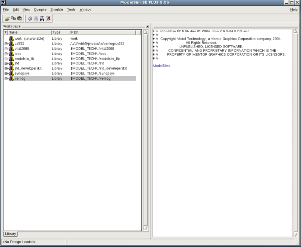 Figure 1 - ModelSim main window
To open a new project, choose File -> New -> Project. Enter tutorial as the project name and cs552_tutorial as the default library name. If a dialog box opens and asks you which version of the modelsim.ini file you would like to use, choose Use Default ini.
You can add files to an open project by selecting File -> Add to Project -> New File. In the dialog box that appears, enter mux2_1 under "File Name". The "Add File as Type" selection box should be set to Verilog and "Folder" should be Top Level. After clicking OK, the newly created file will appear in the workspace project tab. Double click the file name to begin editing the file. Type the code below in the ModelSim edit window then select File -> Save.
        // a 2-1 multiplexer module

        module mux2_1(i0, i1, sel, out);

	  	input i0;

	  	input i1;

	  	input sel;

	  	output out;

	  	reg outreg;


	  	always @* case (sel)

	  	2'b0 : outreg = i0;

	  	2'b1 : outreg = i1;

	  	endcase


	  	assign out = outreg;


	endmodule
Sub modules will automatically work in ModelSim as long as all the needed files are included in the current project. To exemplify this, use the module you just created to construct a 4-1 multiplexer. Choose File -> Add to Project -> New File and create a verilog file named mux4_1. Open the new file for editing and copy and paste in the code shown below.
//a 4-1 multiplexer module
module mux4_1(i0, i1, i2, i3, Sel, out);
input i0;
input i1;
input i2;
input i3;
input [1:0] Sel;
output out;
wire s0, s1;
mux2_1 submod1(i0, i1, Sel[0], s0);
mux2_1 submod2(i2, i3, sel[0], s1);
mux2_1 submod3(s0, s1, Sel[1], out);
endmodule
To compile your newly created files, find the Compile All button found in the ModelSim toolbar located to the right of the paste icon. You could alternatively choose to compile each file individually by highlighting the file in the workspace and clicking the Compile button. The result of the compilation is shown in the right frame of the ModelSim main window. If you copied the code for mux4_1 exactly, you will see a compilation failure shown in red, as seen in Figure 2. To view the error, double click the red line. The window that appears explains that line 13 of the file mux4_1.v has an illegal variable. Double click the error to jump directly to the erroneous line in the ModelSim editor. A quick look at the code reveals that the Sel variable was not capitalized. Fix the error, save the file, and compile again.
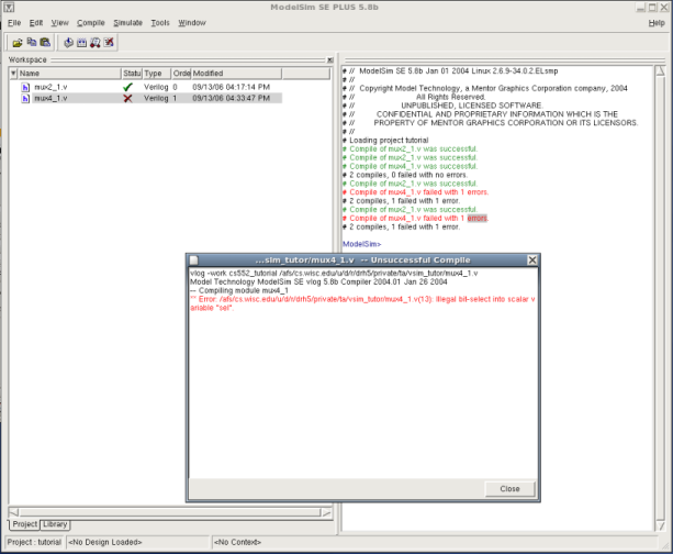 Figure 2 - Viewing a Compilation Error
To simulate a design you must first locate your working library. Navigate to the Library tab in the Workspace window. There you will find the library you just created named "cs552_tutorial". Expand this row to find your design files. Select the top-most design in your project, in this case mux4_1, right click over the name, and choose Simulate.
This will create two new tabs in the Workspace window named sim and Files. The sim tab will contain a hierarchy of modules used in the current simulation, and the Files tab lists the source files used. Open the sim tab, right click on the mux4_1 module, and select Add to Wave. This will open a new "wave" window with the mux4_1 signals already included. You will notice that the internal wires s0 and s1 are present as well. In larger designs it is useful to examine these signals during debugging.
Choose a signal in the wave window and right click to view the options. The Radix option allows you to change the display format of the signal. This is useful for displaying buses in hexadecimal format instead of binary. However, because the mux4_1 module has only single wire inputs we will leave all signals in the default binary format.
Now you will add forces to the input signals so that you can test the multiplexer's function. In the ModelSim main window, choose View -> Signals. This will open a new window that contains a list of all the signals in the current simulation. Highlight the signal i0 and then select Edit -> Force. You should see the screen shown in Figure 3. Set the value of the signal by entering either a 1 or 0 in the Value field and then select the Freeze option in the Kind area. Repeat this step for all the input signals i0-i3 and Sel. When forcing Sel, be sure to enter a two digit binary number.
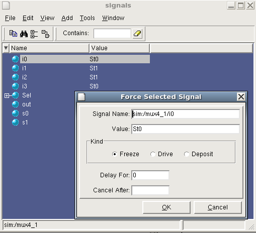 Figure 3 - Forcing signals in ModelSim
After forcing all the input signals, the design is ready for simulation. Navigate back to the waveform window and find the button labeled Run. Clicking this will run the simulation for the default time of 100ns. Clicking the Run button again will run the simulation from the previous stopping point, NOT from time 0. You can test a different set of inputs by switching to the signals window, applying new forces, and running the simulation again.
Clicking in the waveform window will bring up a cursor, which you will see as a vertical yellow line. You can drag the cursor along the simulation timeline to examine signal values. By using the Find next transition and Find previous transition buttons, you can also advance the cursor automatically to the next value change for a selected signal. ModelSim makes it easy to compare the value of a signal at different times by using two cursors. Find the Add Cursor button in the wave window toolbar. Clicking it will add another cursor to the design as shown in Figure 4.
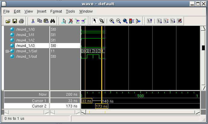 Figure 4 - Using multiple cursors
To end the current simulation, close both the wave and signal windows and navigate back to the sim tab of the main window's Workspace frame. Right click on the top level module that you are simulating, in this case mux4_1, and select end simulation.
When simulating large designs, it is often too cumbersome to manually force a signal using the graphic interface each time you want it to change. ModelSim remedies this by providing a long list of simulator commands. The complete list can be found in the ModelSim help documentation, but for purposes of this tutorial we will cover some of the most commonly used commands.
You will now recreate the simulation you performed in the
previous section using only command line functions. First, you
must initiate the simulation. This is done using the vsim
<library_name>.<design_unit> command (not to be confused
with the vsim command that starts ModelSim from the
UNIX command prompt). To start a simulation of the 4-1
multiplexer, type the following in the ModelSim command window.
vsim cs552_tutorial.mux4_1.
If you do not specify a library name, ModelSim will look for the design in the "work" library.
The next step is to add signals to the waveform. This is
accomplished with the add wave <signal> command. The
signal argument can take the form of a UNIX wildcard string,
i.e. i*, which would include the signals i0, i1,
etc... With the add wave command you can also pass
optional arguments to format the display. Common options are
-color, -<radix>, and
-<format>. See the ModelSim help documentation
for their specific usage and more options. For your simulation,
add all the signals with the command:
add wave *
After signals have been added to the wave file, you must next
force them to run a meaningful simulation. In ModelSim the
force <signal> <value> <start time>
command performs this task. You can specify the type of force
using the options -freeze, -drive, or
-deposit. If no option is used, ModelSim defaults to
the freeze type. The force command can also be used
to create clock signals using the -repeat option.
Consult the ModelSim command reference, found in the help section,
for examples of clock forces. To continue with your simulation,
type the following:
force i0 0 0
force i1 1 0
force i2 1 0
force i3 0 0
force Sel 00 0
force Sel 01 50
force Sel 10 100
force Sel 11 150
The compliment command of force is noforce
<signal> <stop time>.
Now all that is left to do is to run and view the simulation.
You can run the simulation using the run <time>
command.
run 200
To see the results of the simulation, open the wave window by typing
view wave
ModelSim allows you to automate sequences of commands using DO files. The files are simple in structure, containing only comments starting with a # and a sequential list of commands. To create a new DO file, navigate to the ModelSim main window and choose File -> New -> Source -> Do. This will open the editor window with a blank document. Type the following in the editor and then save the file as "tutorial.do".
# reset the simulation
restart -force -nowave
# add all input and output signals to the wave file
add wave -logic i0
add wave -logic i1
add wave -logic i2
add wave -logic i3
add wave -logic Sel
add wave -logic out
# force the input signals
force -freeze i0 0 0
force -freeze i1 1 0
force -freeze i2 1 0
force -freeze i3 0 0
force -freeze Sel 00 0
force -freeze Sel 01 50
force -freeze Sel 10 100
force -freeze Sel 11 150
# run the full simulation
run 200
# open the wave window
view wave
To execute the DO file, type the following in the ModelSim command prompt:
do tutorial.do
One of the most powerful features of ModelSim is it's tight integration with the Tcl/Tk (commonly pronounced "tickle"/"tee-kay") scripting language. Tcl and its graphical extension Tk are interpreted languages similar to python or perl. The Tcl syntax makes heavy use of curly braces and list data types and does not closely resemble any of the common languages such as C or Java. Nevertheless, it is simple enough that meaningful scripts can be created in a short amount of time by learning a few simple rules. While using Tk to graphically represent simulations can be a useful tool, it is beyond the scope of this document. To learn more about Tk scripting in ModelSim, consult the ModelSim SE tutorial found in the program's help documentation.
The real advantage to Tcl scripting in ModelSim is the ability to control the flow of a simulation as you would a sequential program. You can create loops to iterate through a series of forces or format the simulation output to fit your needs. For example, in your 4-1 multiplexer simulation, you can easily iterate through all possible input combinations with a single loop:
    # set the simulation step size as a global variable

    # step is used by both runSim and verifySim listed below

    set step 10


    proc runSim {} {

        # a count of the elapsed runtime

        set runtime 0

         # import the global variable step

        global step


        restart -force -nowave

        add wave *


         # apply all 64 (2^6) possible inputs to the design

        for {set i 0} {$i < 64} {incr i} {

          # force signals based on a mask of the integer i

          force -freeze i0  [expr $i & 0x01] $runtime

          force -freeze i1  [expr ($i & 0x02) >> 1] $runtime

          force -freeze i2  [expr ($i & 0x04) >> 2] $runtime

          force -freeze i3  [expr ($i & 0x08) >> 3] $runtime

             force -freeze Sel [expr ($i & 0x20) >> 5][expr ($i & 0x10) >> 4] $runtime


           # increment the elapsed runtime

           set runtime [expr $runtime + $step]

        }


           # run the full simulation

           run $runtime


        # after the simulation is complete, view the results

        view wave

    }
Notice that ModelSim commands can be mixed with Tcl syntax to
easily control a simulation. To use a Tcl script, add a new file
to your project by selecting File -> New ->
Source -> Other. Copy the script above to the file and then
save it as tutorial.tcl. In the ModelSim command window, type
source tutorial.tcl. This command makes all
procedures in your Tcl script callable from the ModelSim command
window. Run the exhaustive simulation by typing
runSim. When the script is finished the wave window
will appear as shown in Figure 5.
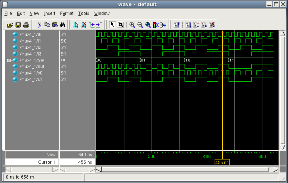 Figure 5 - Result of Tcl Script Call
You can use Tcl scripts to automate design testing. Through
the use of the ModelSim examine command, a Tcl
script can import a signal value as a script variable. This
enables you to create automatic checks for your test cases.
Consider the following function, which, when used in conjunction
with the runSim procedure above, will verify the
results of the exhaustive 4-1 multiplexer simulation.
     # when used in conjunction with runSim,

     # this script will verify that the output of the 4-1 mux is correct.

     proc  verifySim {} {


            # import the global variable step

    	global step

    	# keep a count of the elapsed runtime

    	set runtime 5

    	# set a boolean variable to track if an error was found

             set errorFound 0


         # just as in runSim, apply all 64 (2^6) possible inputs to the design

             for {set i 0} {$i < 64} {incr i} {

	       set i0   [expr ($i & 0x01)     ]

	       set i1   [expr ($i & 0x02) >> 1]

	       set i2   [expr ($i & 0x04) >> 2]

	       set i3   [expr ($i & 0x08) >> 3]

	       set Sel0 [expr ($i & 0x10) >> 4]

	       set Sel1 [expr ($i & 0x20) >> 5]


                # use the 4-1 mux logic equation to determine the correct output

                set correctOut [expr (!$Sel0 & !$Sel1 & $i0) | \


	($Sel0   & !$Sel1 & $i1) | \


	(!$Sel0 & $Sel1  & $i2) | \


	($Sel0  & $Sel1  & $i3)]

               # retrieve the actual simulation output using the examine command

	      set simOut [examine -time $runtime -binary /mux4_1/out]


               # compare the expected output with the actual output

               if {$correctOut != $simOut} {

     	           echo "discrepancy found"

	           echo "correctOut:$correctOut"

	           echo "simOut:$simOut"

	           echo "time:$runtime"

	           set errorFound 1

      	}


            # increment the runtime value by step

               set runtime [expr $runtime + $step]

            }


            if {$errorFound == 0} {

         	 echo "design verified successfully"

            } else {

         	echo "errors were found in the design"

            }

    }
To use the verification function, copy the code above into the
end of the tutorial.tcl script file. After saving,
retype source tutorial.tcl in the ModelSim command
window. You can then verify your design by typing
runSim followed by verifySim.