Project Proposal
Note: this is presented for historical purposes only. Much of the information is out of date.
1. Project Summary
Finite state automata underlie many foundational areas of computer science, including regular language definitions, state machines in programs, model checking, and more. Their simple visual representation makes hand-drawing an automaton on paper or a whiteboard the typical first step of implementation. However, the translation from a visual representation to a working implementation is often tedious and error-prone. This project aims to create a system that takes a hand-drawn automaton, derives logical constraints from the image, and synthesizes an implementation of the desired automaton.
Solving this problem is important because it will reduce the time and potential for bugs when implementing systems based on automata. This reduction enables software developers to focus more on the program logic and less on the minutia of implementation. I am personally interested in this problem because my area of research is in program synthesis, and an image-based program specification is novel in this area. Plus, I have at many times had to do this automaton-image-to-implementation translation manually, and it was time-consuming and error prone. Having a system as proposed would have been beneficial to me.
I was not able to find prior work for this exact problem. Similar approaches either rely on drawing the automaton on the computer (so the system is directly told all constraints and is simply rendering the automaton), or direct input of the automaton constraint. Using an image as a program specification in this manner appears to be mostly1 novel. Existing approaches either are focused on UI design (e.g., Microsoft’s Sketch2Code) or synthesizing image manipulations (e.g., using the actual image data as a specification), as opposed to specifying an executable program through diagrams in an image (e.g., extracting features and text that specify a program). For this particular case of automata, deriving a specification from an image is a natural step forward for usability.
While the overall application is a new approach, my implementation will use existing computer vision techniques for recognition of the automaton pieces images, as well as standard program synthesis techniques for automata synthesis. Specifically, my goal is to compile the synthesis program into a semantics-guided synthesis (SemGuS) problem, which is a general synthesis framework and the focus of my main research. Once compiled to a SemGuS problem, any SemGuS solver can be used to synthesize the automaton implementation.
Evaluation of this system is relatively straight-forward, based on the following questions.
- Can it successfully turn automata images into implementations?
- What sorts of automata can it can handle?
- Under what conditions does it fail?
Evaluation will include creating “benchmark” images of varying difficulty. As the focus of this project is on the computer vision side, the evaluation will be oriented more toward the produced automata specifications rather than the final synthesized programs. In particular, one caveat is the maturity of SemGuS tooling—it is still under active development and may not be stable enough to solve these automata problems.
2. Timeline
A proposed timeline is as follows:
| Date | Tasks |
| Week of Feb. 28th: | Initial project planning. Set up vision pipeline. |
| Week of Mar. 7th: | Item detection: states and transitions. |
| Week of Mar. 14th: | Constraint compilation: transition relations. |
| Week of Mar. 21st: | Item detection: positive and negative examples. |
| Week of Mar. 28th: | Constraint compilation: examples. |
| Week of Apr. 4th: | Integration with \textsc{SemGuS} tooling. |
| Week of Apr. 11th: | Create benchmark images and test. |
| Week of Apr. 18th: | Continue testing and evaluation. |
| Week of Apr. 25th: | Final touches and presentation. |
3. Example
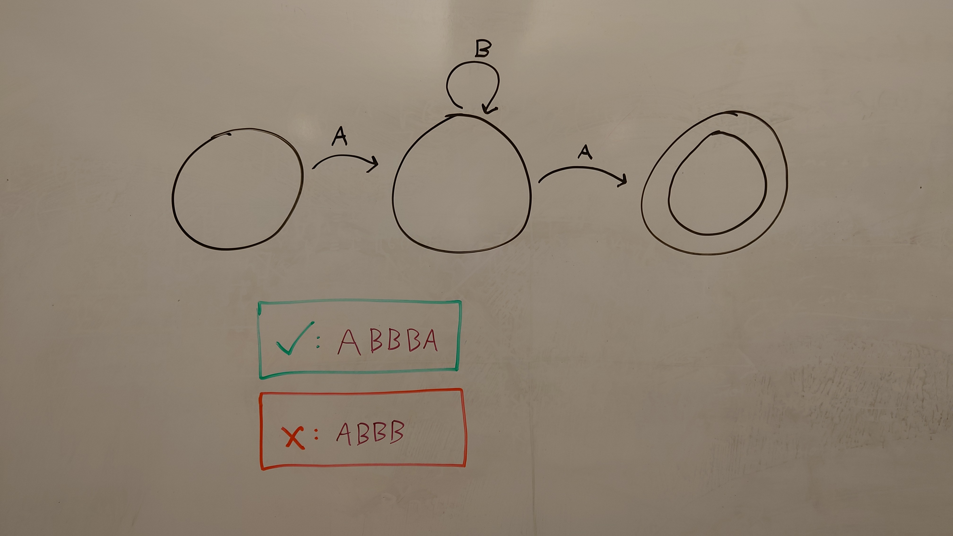
Figure 1 shows an image of an automaton defining the regular expression \(AB^*A\), as well as a positive and a negative example. This image would be compiled into the following constraints, written here as constrained Horn clauses (CHCs). First, three states are defined:
There are additional constraints distinguishing the accepting state (double circle) and non-accepting states:
The transitions (arrows) between states become:
The examples become additional constraints:
where \(Execute\) is a relation that holds when the automaton is run from initial state \(s_0\) on the given string and halts at state \(s’\). The exact form the examples will take on the image is not yet decided; the presented form of a check or cross followed by the example seems reasonable for now.
Note that these specifications are not a complete description of the system. In particular, no starting state was specified in the image, and there is an implicit failure state for when no transitions apply. While these are necessary for a real implementation, drawn automaton often omit these, and so we use program synthesis to find the most reasonable implementation (aided by the given positive and negative examples).