Panoramic Mosaic Stitching
by Steven Kappes
Description:
I implemented panoramic mosaic stitching algorithm with the common steps: remove radial distortion, warp the images to a cylinder, stitch the images together, and use an affine transform to crop the final image.
Removing radial distortion and warping the images to a cylinder was done with inverse warping. The inverse warp checked where each pixel's neighbors mapped to to determine the convolution kernel size.
To stitch the images together, I first made a large blank image and copied the first image to it. Then for each image, I computed the homography between the previous image and the next image with Sift to detect common features. The homography generated is usually very close to the identity matrix plus a translation. To remove potential errors from accumulating, the non-translation elements of the homography is reset to the identity matrix. The image is then composited to the large intermediate image created earlier. After each image is copied to the composite image, the homography is multiplied by all the previous homographies to convert the next image. This is slightly different than recursively merging the first two images until only one is left, but I didn't want to run Sift on large images. As a result, my program assumes that the images will be stitched together in a clockwise direction. It is up to the user to ensure this is how the images are listed in the image list text file.
Once all the images are composited including the initial image copied to the end, an affine transform is used to crop the image. This is computed by finding the two midpoints on the top and bottom of the first image and the corresponding points of the last image. The corresponding points are found using the final homography. These points are guaranteed to form parallel lines since only translations are used to stitch images. Therefore, when the homography between these points are calculated, this will be an affine transform.
Program Usage:
My program is written for Visual Studio 2005. It relies upon libgil2 for loading and saving images and GSL for solving the linear systems. The pre-compiled versions of these libraries can be found here and here. Sift is also required to be in the directory the program is run in for feature detection. The compiled executable of my program and Sift is also include.
When my program runs, it will prompt you for a image list file. The path you need to enter is relative to the path of the program. The image list text file must be formatted like so:
<Number of times to rotate the images counter-clockwise>
<Camera focal length in pixels> <K1> <K2>
<Number of pictures>
<Image file path>
<Image file path>
...
The path image file path is again relative to the path of the program. The images must be in clockwise order for program to stitch them together correctly. The focal length, K1, and K2 can be floating point numbers. The number of times to rotate the images is helpful so you do not have to manually rotate all the input images if they are sideways. If the file is not formatted as my program expects, it should give a reasonable error message. Here is an example of the image list file used for the pictures I took.
The program can also be ran automatically with command-line arguments. The command-line arguments need to be in this format:
p2 <image_file.txt> <print debug info>
Setting the print debug info to anything but 0 will display extra information when the program runs, particularly the values of homographies used to stitch the images and the final cropping homography.
The output of the program will be the panoramic image "result.jpg" in the same directory as the program. For instance, if you run the executable as "p2 image_list.txt 1", result.jpg will be produced from my photographs. A few temporary files are also produced: tmpImg.pgm (used for Sift feature detection), tmpKeyFile.txt (Sift features), and tmpResult.jpg. tmpResult is the composited image and is updated everytime images are stitched together. This can be viewed as the program is running to see how the final image is produced.
Results:
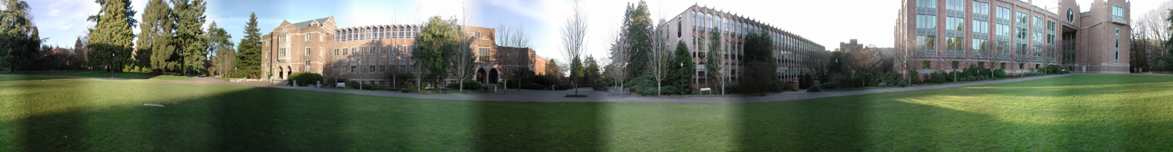
My images I photographed myself are here. The resulting panoramic image is here. I also included the result of the test images which is here. This shows the blending between images which have different brightness. I used a blend window of 75 pixels. This could easily be changed in my program, but there is no option for the user to change this though.
I chose the panoramic image above generated from my photographs as my artifact. Here is the resulting panoramic image:
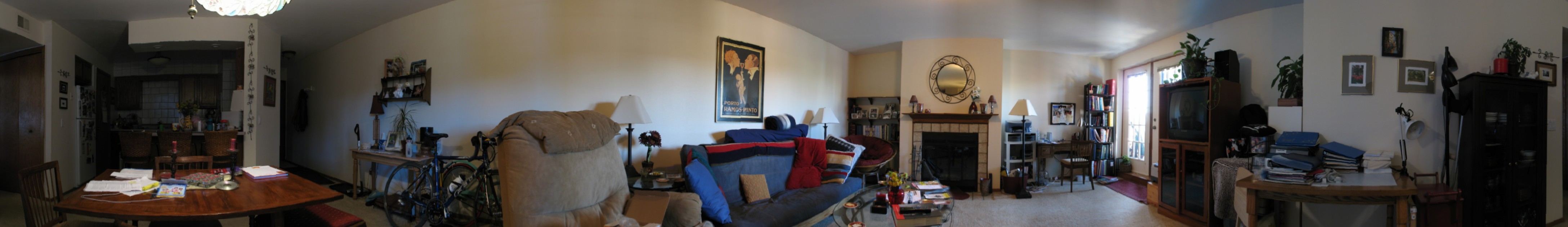