 --------------------
CS 766 Project 2 Report
Jake Rosin
10-9-07
Project Description
Use image stitching to combine a set of photos into a panorama. Photos to be combined should be taken using a Kaidan head, or some other technique to ensure the camera center remains stationary for the entire process. The implemented program should warp the source images as necessary to correct for radial distortion, project the images onto a cylinder, align successive images and render the result by unrolling the cylinder. Linear drift accumulating when the images are aligned must be corrected, and the result cropped, before the final panorama is output.
Algorithms Used
Removing Radial Distortion: Since the focal length f and coefficients k1 and k2 were provided for the cameras used to capture the images (one camera for the test images provided, another for those I took myself), radial distortion can be easily corrected. The point (x,y) in the undistorted image is related to (x',y') in the distorted image as follows ( (x_c, y_c) defines the center of the image):
x_n = (x – x_c) / f
y_n = (y – y_c) / f
r = sqrt( x_n^2 + y_n^2 )
x_d = x_n ( 1 + k1r^2 + k2r^4 )
y_d = y_n ( 1 + k1r^2 + k2r^4 )
x' = fx_d + x_c
y' = fy_d + y_c
To construct the distortion-free image we iterate through its soon-to-be-pixels, use their values (0,0) through (imgWidth, imgHeight) as the values of (x,y) in the equations above, and derive the point (x',y') in the distorted image whose value corresponds to (x,y). Note that (x',y') may be between pixels in the distorted image; the procedure to estimate its value is discussed in the section on interpolation.
Cylindrical Projection: A similar process is used to map the corrected image onto a cylinder. This step is necessary to create a panorama which yields 360 degrees of view; the naïve approach of using homographies to warp all input images to match the first will result in a mosaic which approaches 180 degrees asymptotically (see the lecture slides from 9/18). Cylindrical projection can be understood intuitively: picture standing in the center of a glass cylinder, looking at the source image through the glass. Cylindrical projection paints a distorted version of the image onto the surface of the cylinder such that from your point of view in the center the image is unchanged – a ray from your eye (in this hypothetical you are necessarily cyclopean) will pass through the cylinder at a point (x_cyl, y_cyl) in the projected image which corresponds to the point (x,y) in the source image along the same ray.
As with our correction of radial distortion, we work by-pixel in the projected image, finding points in the source image which correspond. The equations to do so follow.
Θ = (x_cyl – x_c) / f
h = (y_cyl – y_c) / f
^x = sin Θ
^y = h
^z = cos Θ
x = f( ^x / ^z ) + x_c
y = f( ^y / ^z ) + y_c
Image Alignment: Images are aligned in pairs, moving around the cylinder, finally stitching the last image to the first (actually we add another copy of the first to the end of the panorama, then chop off 1/2 its width from both ends, but the two are equivalent). We use feature-based image alignment. First SIFT is used to identify features within the two source images, and the translation between images is estimated using feature matches. The details of this step are discussed in their own section below.
The result of this is a translational shift between each pair of images. Such a translational shift is not likely to be by whole pixel values, so at least one of the images must undergo translational warping before the two are combined.
Blending: When image pairs are combined the seam is likely to be visible due to variance in pixel values and brightness. I implemented a feathering algorithm to blend images and reduce seam visibility. Define x_start as the column where the image on the right begins and x_end as the column where the image on the left ends. The value of a pixel in column x, where x_start <= x <= x_end, is found using:
w_left = 1 - ( ( x – x_start ) / ( x_end – x_start ) )
w_right = ( ( x – x_start ) / ( x_end – x_start ) )
x_val = x_leftVal ( w_left ) + x_rightVal ( w_right )
This relatively simple algorithm was found to be perfectly suitable for the images used; I could identify no seams through visual inspection of the panoramas produced (aside from the panorama made from the test images – see the section on results).
Correcting Vertical Drift: Slight vertical drift at each image pair can accumulate as the panorama is constructed. The amount of vertical drift can be checked by added the first image to the end of the panorama and computing the vertical difference between the centers of the copies at either end of the panorama. A linear shift is sufficient to correct for this: a can be trivially found as the slope of a line connecting the two centers. The y coordinate of any point (x,y) in the mosaic is shifted as follows:
y' = y + ax
Finally, half of the first image is removed from the beginning and end of the panorama, so that the two edges line up perfectly to form a 360 degree view. The image is vertically cropped to remove any undefined pixels and the resulting panorama is output.
Implementation Details
The Gil library was used in this implementation to aid in image manipulation and I/O. The Gil installation used for Project 1 was also used here; the library was downloaded from https://www.cmlab.csie.ntu.edu.tw/trac/libgil2/wiki/Download and installed using the instructions provided on the CS 766 course page. The SIFT program was also used; cylindrically projected images are written to disc as PGM files, SIFT is run, and the resulting text files are read back into the program to gain image feature information. All other functionality was hand-coded by me (aside from functions in the C++ standard). Code was written, compiled and tested on an Ubuntu Linux 7.04 system.
When run, output from SIFT is printed directly to the console. The horizontal and vertical translational motion between each pair of images is also displayed, once it is calculated.
The executable produced must be run from the same directory in which SIFT is located. See the README for details.
Finding Image Alignment
I initially implemented a placeholder algorithm for computing image alignment, to later be replaced by RANSAC. However, when I began generating panoramas I could detect no alignment flaws, making the added complexity of RANSAC seem unnecessary. RANSAC is a feature-based method of finding a full homography between two images; however, for the images I used a translational mapping was sufficient. The details of RANSAC are available from the 9/27 lecture slides; I will describe my simpler translational mapping heuristic here.
1) Use SIFT to find the features in images I_1 and I_2.
2) Pair each feature f_1 in I_1 with the closest match f_2 in I_2. Call f_2 the 1NN of f_1. Also find the second best match in I_2, 2NN. Keep the feature pair (f_1, f_2) as a good match if dist( f_1, 1NN) <= 0.6( dist( f_1, 2NN ) ). The threshold value 0.6 was suggested by the SIFT documentation. Discard all feature pairs which do not meet the qualifications of a good match.
3) Each feature pair defines a translational vector. Iterate through the vectors, grouping each with any previously seen vector with less than 1 pixel difference (the ordering of vectors is theoretically important for this step but I haven't seen it make any difference).
4a) Using the translational vector from the previous image pair V_t-1 as a guide, choose G as the most populous group where the average length len( A ) satisfies 0.9( len( V_t-1 ) ) <= len( A ) <= 1.1( len( V_t-1 ) ). This restriction is intended to maintain “momentum” as the panorama is being constructed. When it was omitted, occasionally estimated translational motion between image pairs was found to be wildly inaccurate. Note that the use of momentum assumes the first image pairs are correctly aligned by the algorithm, but if this is not the case the order the images are presented in can be easily changed.
4b) If no such group exists, this the first image pair, or for some reason we expect the translational motion to differ greatly from the previous image pair, we simply choose G as the most populous group.
5) Find and return the vector V_t within G which is closest in Euclidean distance to A, the average shift for all vectors within G.
One side effect of this heuristic is that estimated translational motion is defined both by a shift, and in terms of the most representative feature pair. My implementation uses this feature pair as the “anchor point” between images – when they are joined in the panorama the images will be placed such that these features exactly match.
Planar Mosaics
Since the image alignment heuristic makes no assumptions about the direct of translational motion (aside from the momentum restriction, which may be omitted) it can be used to stitch images which do not form a cylindrical panorama. My implementation can thus construct planar mosaics in addition to panoramas, so long as the camera itself is only translated (not rotated), since only translational motion can be corrected. Replacing my alignment heuristic with a full RANSAC implementation would relax this restriction and allow arbitrary camera positioning for capturing source images.
As a proof-of-concept, source “images” were formed as sections from one source photograph found online (photographer unknown). These sections represent translational motion of the camera over the planar scene, and were thus correctly stitched by my program. Radial distortion is corrected by my program even when generating planar mosaics (in this case with f = 100000000000000000000, k1 = 0, k2 = 0), so I see no reason why true source images of a planar scene would not be correctly stitched, assuming the camera maintained the translational restriction during the photography.
Interpolating Once
Image warping is performed by my program by constructing a mapping from each pixel in the resulting image to a location in the original. Once this mapping is found the value of each pixel in the warped image is interpolated using the four nearest pixels to the point in the original. A weighted average of the four values is calculated, with the weight for a given pixel being the coverage in square pixels. By definition, w >= 0 and the four weights sum to one. Any point which is not contained within the original image is set to black. Interpolation introduces a small amount of blur to the image, and can lose data around the image's edge.
Since mapping and interpolating pixel values are two distinct steps, the later can be postponed until a rendered version of the image is needed. One result of this is that consecutive mappings may be applied and interpolation performed only once. Combining multiple interpolations in a single pass keeps their negative effects from accumulating.
Warped version of the input images must be rendered in order for SIFT to identify features within them. After this, the images are aligned and pixels are blended to join them seamlessly – stitching and blending requires another interpolation (in this case, merely a translational one, but blur still occurs). A final warping and interpolation is necessary to correct vertical drift – three interpolations in total. The accumulated blur from these interpolations is slight, but noticeable.
My implementation uses a WarpedImage class which retains the original image data and warp mappings after interpolation. Subsequent warps may be performed and the image reinterpolated using this pair, with the rendered result having undergone only one interpolation. This capability is used to produce a panoramic image which has been interpolated only once.
The mechanics of bypassing the first interpolation are simple – a rendered image is passed to SIFT, while the <original image, warp mapping> pair is kept internally for the additional transformations. Skipping the second interpolation is a little trickier, since the panorama cannot be constructed without translation and blending. We accept this, getting an interpolated result from which the value a can be calculated. We then apply the vertical linear shift to each source image – still represented as a pairing between the original image and a warp mapping – and reconstruct the panorama using the results. This produces a panorama which has undergone exactly one interpolation.
The final step above – recreating the panorama using vertically shifted source images – is aided greatly by the specifics of the image alignment heuristic. Since the output of the heuristic is a pair of features which correspond, the image pairs can be easily joined at this feature even after being warped (the location of the feature is shifted along with the image itself).
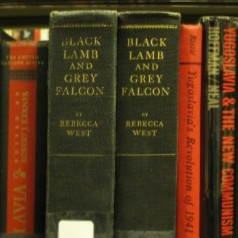
Shown below are sections taken from panoramic results of my implementation – one created using only a single interpolation, the other using three as described above. It should be noted that the second interpolation is not strictly necessary, even if image mapping information is to be discarded at each step, since the vertical drift can be calculated using the relative shifts between images (computable without any image warping beyond distortion correction and cylindrical mapping), but since this was not the method described in the assignment I count omitting this interpolation as a gain.
--------------------
On the left, a portion of a panorama interpolated exactly once. On the right, the equivalent portion of a panorama formed the same way, with the exception that three interpolations were performed sequentially at the times described above. Notice the slight blur in the version on the right, especially apparent in the text and texture of the book spines.
Results
Excellent. All five photo sets taken rendered correctly using the method described herein. They are available at http://pages.cs.wisc.edu/~rosin/cs766/panorama/ in low-res, full-size and embedded versions. The only problems noted are ghosting / doubling of elements which moved between shots, such as the young woman in offkilter.jpg and the tree branches in lake.jpg. Since these elements were not static when the photos were taken, they cannot be corrected by the techniques described in the assignment. The slight variance between affected images did not affect alignment results.
The planar mosaic proof-of-concept image was also a success. It is not hosted online, but can be found among the files submitted in the “planar” subdirectory.
The only problem I found with generated mosaics was, oddly enough, in the provided test images. The panorama formed using them shows vertical lines of brightly colored pixels. Since the lines don't appear in any of the source images I assume they were introduced by my program. I could not replicate this bug using other source images, nor isolate it to a particular component of my implementation. The blending seams were also more visible in the test panorama, but I attribute this result to inexact values for the focal length and radial distortion coefficients, causing image misalignment.
I had difficulty choosing a favorite of the five panoramas; all have a special place in my heart (with the exception of woods.jpg, which seems a bit mundane compared to the rest). Nevertheless I have selected books.jpg as my favorite. It can be found here.
Additional Work & Functionality
Planar mosaic construction, under the restriction that the camera movement is approximately purely translational (for example, a downward-facing camera mounted on a plane moving along a single vector, or scans of sections of a larger document kept in the same orientation), is implemented. Planar images are imported the same way as panoramic ones, except that the .meta file begins with the keyword “planar” (see the README for details). Implementing RANSAC is the only necessary change to allow unrestricted planar mosaic construction.
Single-pass interpolation is implemented as well. This allows a mosaic with slightly more detail than one constructed using the assignment instructions. The code which retains image/mapping data as separate components from which rendered images can be derived at will is encapsulated in the WarpedImage class and is thus fully portable to other applications (it relies on Gil but no other portions of my code).
Five panoramic images were created from scratch.