Original Photos of Building | ||
|
| |
|
Self Calibration |
The Problem: Given a series of views of a static scene, all taken from the same camera with unvarying internal parameters, calculate the internal camera calibration from the views alone (without any extra information such as measurements in the scene).
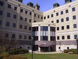
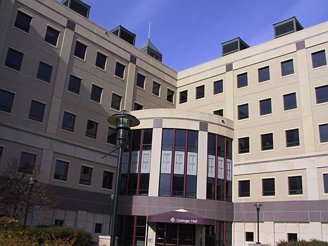
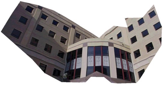
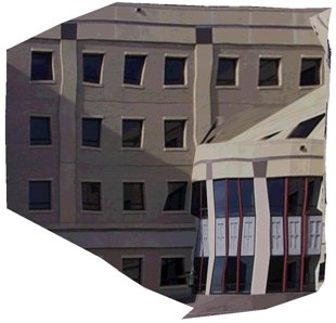
Example: To begin the self calibration process, I took 7 photos of a building of which 2 are shown below:
Original Photos of Building | ||
|
| |
Determining self calibration is equivalent to finding a particular location X in a search space. Recall that for each pair of photos in the original series, there is a corresponding fundamental matrix. Each fundamental matrix induces a screw-transform manifold in the search space (a manifold is a surface in R^m that behaves locally like R^n (n < m), and in particular, has a local coordinate system comparable to R^n). The desired calibration point X is the intersection point of all the screw-transform manifolds.
Screw-transform manifolds tend to be well-behaved mathematical structures, meaning they tend to have gentle and limited curvature. This is demonstrated in the three screw-transform manifolds shown below, and also in the screw-transform manifold gallery. Notice in particular the regular grid imposed on each manifold; this is the coordinate system of the manifold.
Three Screw-Transform Manifolds |
|
To find the fundamental matrices, I identified by hand about 100 point correspondences between each pair of images (note that other researchers have created automatic point-tracking software for this purpose, so user interaction is not necessarily required). To make the job easier, the same 100 points were tracked through the entire sequence. Next, a RANSAC technique was applied to the point correspondences to find the fundamental matrices.
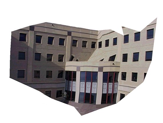
Self calibration was determined by finding the mutual intersection point of all the screw-transform manifolds. A voting scheme was used for this purpose. Once the internal camera calibration had been determined, scene reconstruction was possible. The tracked scene points were reconstructed in 3D and Delauny triangulation was used to create a 3D model with surface texture. Three views of the model are given below:
|
|
|
"Waviness" in the model is the result of inaccurate point correspondences; remember the correspondences were chosen by hand and are only accurate to within a few pixels. Even a small error in correspondence can result in large 3D errors. Other researchers (e.g., Koch) have demonstrated excellent automatic point correspondence software that can reduce this source of error. Note that the problem of point correspondence is separate from the mathematics of self calibration that I have been researching.
Also observe that the original photos were taken from ground level
while two of the model views given above are mid-level views. Thus
the roof of the quarter-circular annex was not visible from ground
level and is filled-in with sloping triangles in the model, resulting
in significant texture errors in the roof area.
|
Russell Manning / rmanning@cs.wisc.edu / created 01/22/02 / last modified 01/10/03 |