BambiSim provides full functional simulation of the BAMBI architecture. It also includes full and mostly accurate emulation of the I/O hardware. During the course of software development a debugger was added to the emulator. The debugger supports basic functions such as break points, asynchronous breakpoints, single stepping execution, runtime disassembly of executed instructions, memory examination, and stack traces.
The main loop of the emulator simply fetches an instruction and then executes it. There is a global structure that keeps the state of the entire processor, including register values, PC and also breakpoints. For execution there is a large switch statement for the current instruction's opcode. Each opcode case performs operations on the global 'bambi' state variable. Memory accesses are passed through a function that catches accesses to I/O space and passes those onto the respective emulation functions (spart_read(), spart_write(), etc...)
Interrupts are checked for in every pass throught the main loop. When one is detected, a normal interrupt is emulated. Calling the spart_intr() function allows the spart emulator to count how many cycles hace gone by, so it is able to correctly emulate how often characters are passed back and forth between the emulated SPART and the terminal running the emulator.
The debugger function is called every step throught the main loop. It checks to see if there is a breakpoint at the current cycle, if there is, the debugging loop is activated, keyboard I/O is redirected to the debugger rather than the SPART emulator, and a debug prompt is given. The debugger has full access to the machine state so it is easy to add any functionality that might be desired.
The debugger was modelled after gdb. This is an example debugger session, a breakpoint was previously set at 0x63c:breakpoint at 0x0000063c... bambi debug> h x- examine n words of memory at s - single step execution n - execution until pc+4 is reached bt - stack trace br - insert breakpoint at bp - print active breakpoints d - delete breakpoint at p - register dump t - toggle trace enable q - exit bambisim c - continue bambi debug> p Bambi State: timer:0x00000063/0x00000200 PC: 0x0000063c enabled exceptions: syscall bad_instr bad_addr priv_viol timer spart active exceptions: syscall r0 : 0x00000000 r1 : 0x00006c0c r2 : 0x00000000 r3 : 0x00006220 r4 : 0x00000001 r5 : 0x00000000 r6 : 0x00000000 r7 : 0x00000000 r8 : 0x00000000 r9 : 0x00000000 r10: 0x00000000 r11: 0x00000000 r12: 0x00000000 r13: 0x0000d9cc r14: 0x000001dc r15: 0x00000000 r16: 0x00006220 r17: 0x00000000 r18: 0x00006220 r19: 0x00000000 r20: 0x00000000 r21: 0x00000000 r22: 0x00000000 r23: 0x00000000 r24: 0x00000000 r25: 0x00000000 r26: 0x00000000 r27: 0x00000000 r28: 0x00000004 r29: 0x00006220 r30: 0x000003e8 r31: 0x00006c1c mode : 0x00000001 epc : 0x000001dc cause: 0x00000002 mexa : 0x00000000 emask: 0x0000007e base : 0x00000000 bmask: 0x0003ffff spr7 : 0x00000000 bambi debug> s PC: 0x0000063c (0x18f)(0x88) lw r17, 12 (r16) (0x00000003) (addr = 0x188b) bambi debug> PC: 0x00000640 (0x190)(0x18) addi r3, r0, 1 (0x1) bambi debug> bt 0x00006c0c) 0x00006c20) return address: 0x000003e8 0x00006c40) return address: 0x000000e0 bambi debug>
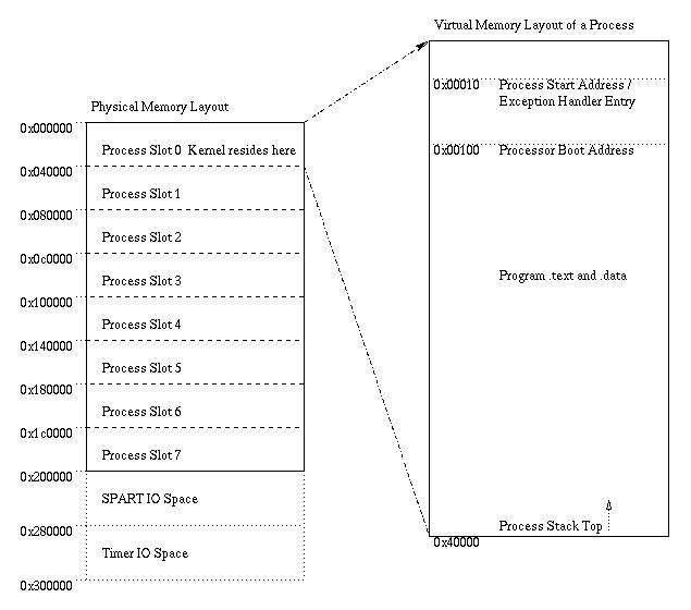
ThumperOS is a very simple time sharing operating system. It currently supports up to 7 user processes and basic asynchronous serial I/O. Process switching is done with a strict round-robin scheme where switching occurrs whenever there is an exception. Also implemented are blocking system calls, so that processes awaiting an event are completely stopped from running until the system call completes.
There are 8 memory slots set up by ThumperOS. Although these could be somewhat arbitrary defined, they are currently hardwired to each take 1/8th of the available physical memory. The zeroeth slot is where the ThumperOS kernel and its data structures reside.
After the initial system setup, the kernel reverts to a purely exception driven mode. There is one kernel entry point and one register which contains a bit for each exception that is active. The interrupt handler handles each active interrupt and then clears the corresponding bit in the cause register.
At the end of the interrupt handler a round robin algorithm is used to decide what process will be run next. When a process is chosen from the que, it is first checked to see if it is blocked. If it is, the kernel syscall() function is called to try to complete the blocked syscall, if that works, the process is run, if that fails then the next process in the round-robin is tried. If all of the runnable processes are blocked, or if there are no runnable processes, then the idle process (slot 0) is scheduled. Finally, when a process is selected, the rfi() function takes a pointer to a structure that contains the full machine state to be loaded for that process. We did not implement kernel threads. Although that would have been fully possible, there was no real gain to doing so because the services offered by the kernel were relatively unsophisticated.
In our design, both the processor's Memory Stage and the ICache need access to main memory. To handle arbitration between them, we have a memory controller. The memory controller provides two functions: it does arbitration and also generates signals that drive the memory's control signals based on the results of the arbitration.
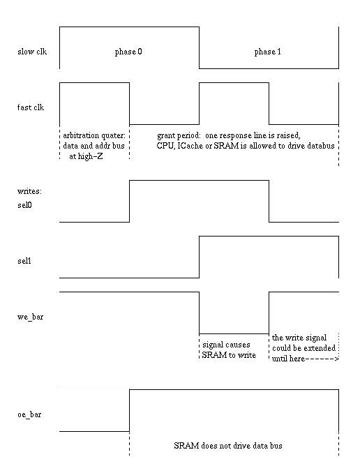
Arbitration requests are made and responded to in a single cycle. Memory accesses are also performed in that same cycle. This is possible to do by using a clock twice as fast as the Processor and ICache clock. The memory controller has four states spread out over one cycle of the main clock. The first of these states enforces a high-Z state on the memory bus between operations (between slow clock cycles.) The final three states send the signals necessary to do a read or write to memory.
The high-Z state does two things, it ensures that no device is writing the bus, and it also accepts memory requests from the Processor and ICache and decides which device is allowed to use the memory. At the end of this state, a response line is raised to either the Processor or ICache, that response line is used to control a tri-state buffer driving the address and data busses. This scheme allows the CPU or ICache to do a memory operation on the same cycle in which it issued a request. This strategy worked at fast_clock speeds up to speeds of at least 20MHz (the actual requests ran at 10MHz.)
The final three states of the memory control continue to keep the response lines high. In case a memory write was requested and granted, the memory controller must produce the correct output on the sel0 and sel1 lines to produce correct and safe output enable and write enable signals for the SRAMs.
The one-quarter clock cycle write time was probably the limiting speed factor in our design. With slightly more complex bus-driver control we could probably double the time which the write enable is active, probably nearly doubling the memory bandwidth. This would be done by merging the initial quarter clock cycle where neither the CPU nor the ICache are allowed to drive the bus with the final quarter clock cycle during which the SRAM is not allowed to drive the bus. The SRAM's output enable would then need to continue to be disabled in the beginning quarter cycle of a slow clock cycle following a write.
At some point we realized that the SPART Mini-project that we had done was not functionally correct, so we had to re-write the baud generator and receive unit portions of the SPART. Our original SPART design only sampled the incoming RxD line once every bit-time, this was a design flaw that happened through misinterpretation of the Mini-project handout. The new baud rate generator has two clock outputs, one that triggers once every 16th of a bit-time, and one that triggers once every bit-time, as the old baud generator did. The 16th rate clock is used in the new receive unit to take 16 samples of each bit to make sure that clock skew between the SPART and the remote end does not cause errors. The results of 16 samples are tabulated and used at the end of the bit-time to decided whether the bit was a '1' or a '0'. This provides far better accuracy in data transfer.
This trace shows a byte coming into the spart on RxD, and the same byte being echoed back on the TxD line. Also clearly visible are the slow enable and fast enable signals that determine bit length and sampling times, respectively.