I've been looking for an inexpensive antenna tuner with a roller inductor for a while -- "inexpensive" is why I've been looking for a while. Not sure why -- I have one of those LDG auto tuners that works just fine. So, when a tuner with a roller inductor finally came my way, I figured out what I was going to do with it -- make it an auto-tuner.
In April/May/June 2002 issues of QST, W8ZR presented his EZ-tuner project. This is a T- network tuner controlled by BASIC Stamp (remember those?). According to the project site, this is more of a memory tuner -- all matches need to be set ahead of time and will be selected based upon recalled frequency. It also looks like the inductor is fixed with taps.
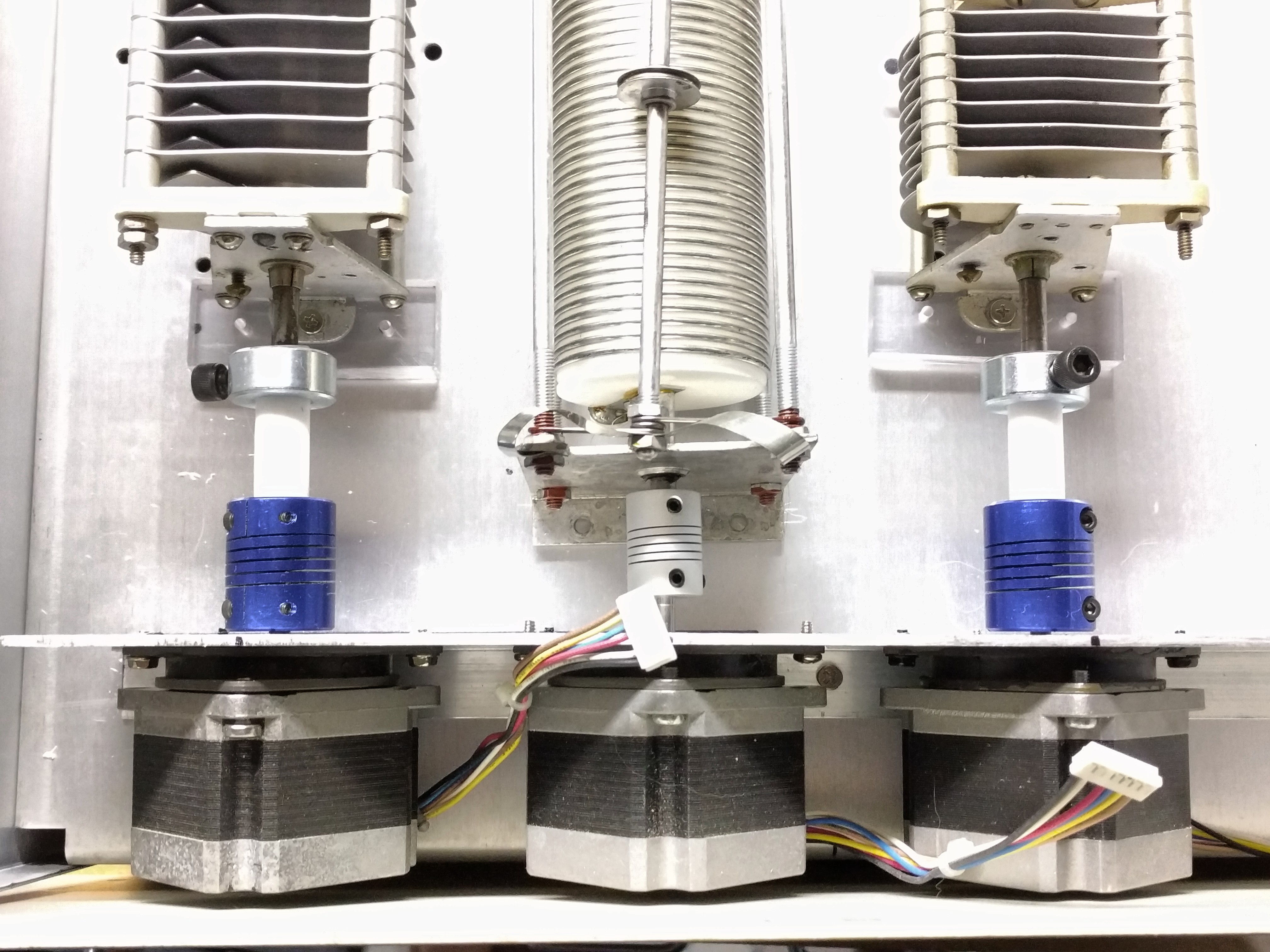
My goal is to use a stepper motor for each of the capacitors and the roller inductor controlled by an Arduino Mega. Match will be determined by sensing forward and reverse power and optimizing by some algorithm TBD. I would also like to integrate two radio inputs, three antenna output and bypass/through functionality.
Starting materials
The tuner I started with is an SPC design -- series/parallel capacitor. Note the ganged but isolated capacitors on the output.
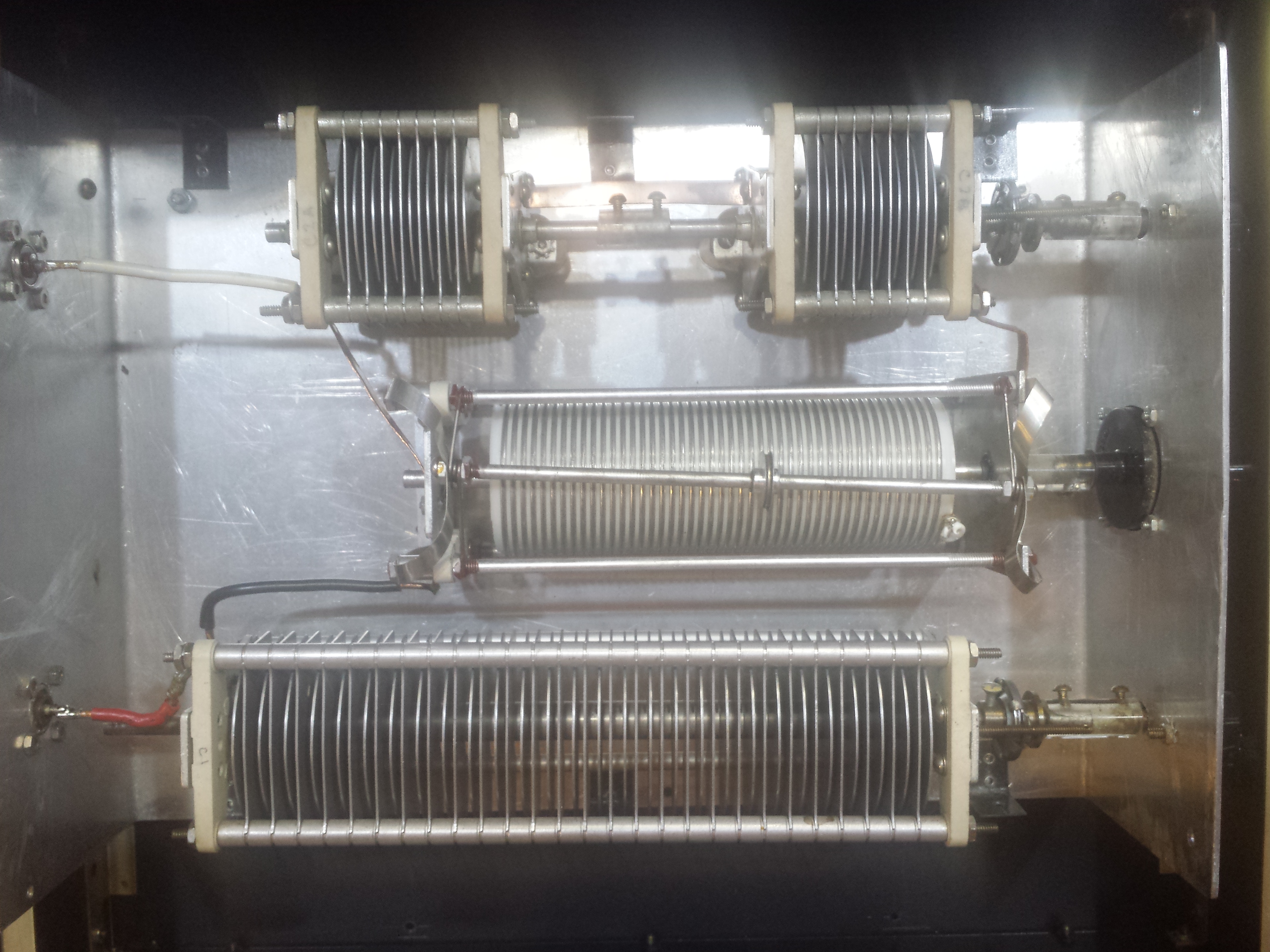
The SPC tuner design has an output capacitor in parallel and in series with the inductor. I guess this gives some harmonic attenuation and wider tuning range for the cost of twitchier tuning and higher loss. That all remains to be seen, I guess.
Proposed layout
I picked up a decent 2U somewhat deep rackmount chassis for $5 and it looks
like everything might fit. Proximity of the components to the chassis may
reduce the maximum power through the unit but will all probably be fine for
the 100 watt maximum I have.
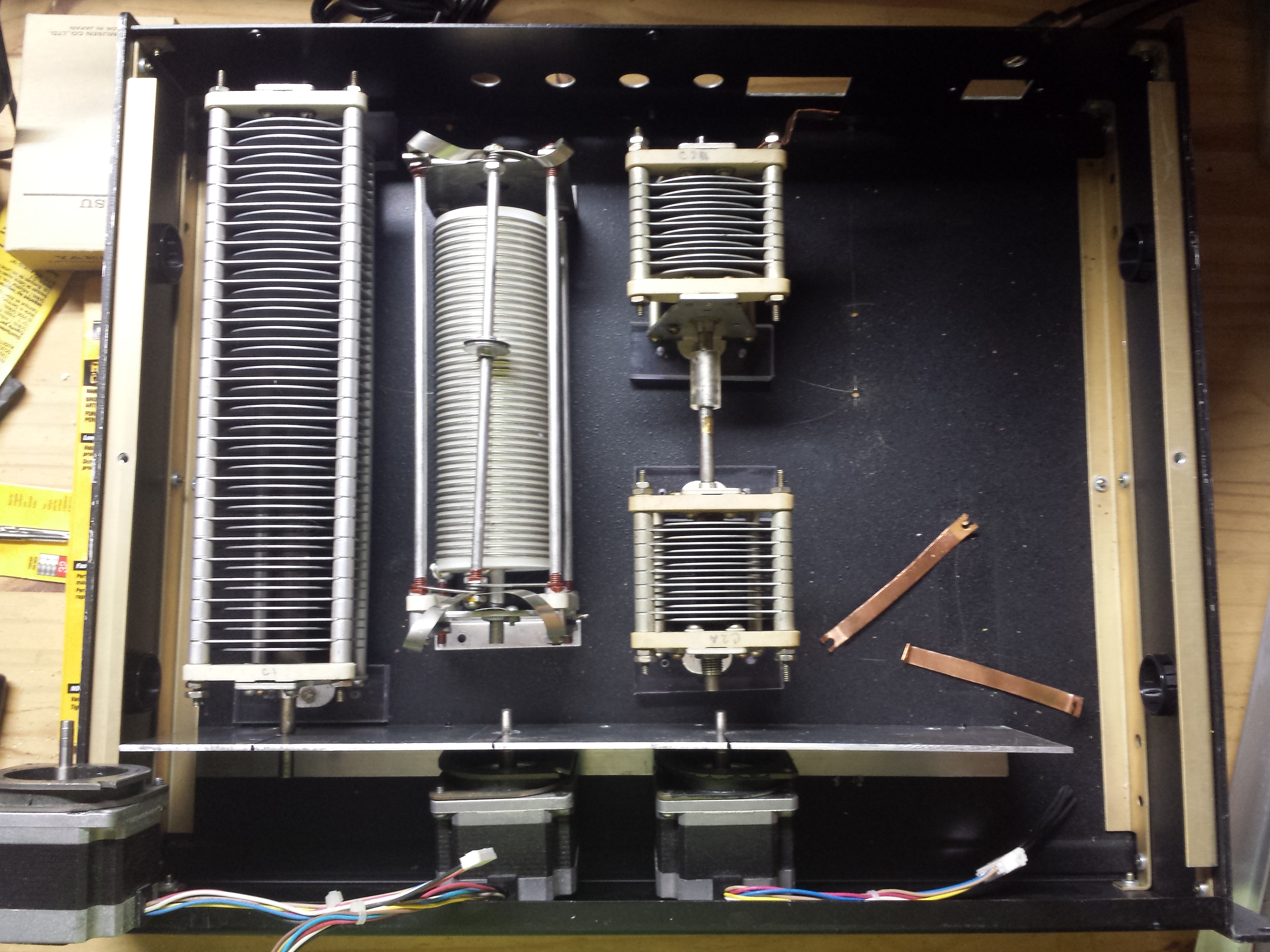
The front of the tuner will have an aluminum panel on which the NEMA23 stepper motors are mounted. These will be coupled to the components via what I currently suspect is going to be fiberglass rod. The right side of the case will have switching, sensing and electronics.
The components are mounted off the chassis with some plexiglass spacers which should be adequate for the 100W I anticipate.
I came across an interesting find -- the RAMPS 1.4 3D printer controller integrates a display, stepper drivers, sensor switches and a bunch of other stuff along with an Arduino Mega into an inexpensive and small package. I'll need all of the stame stuff for the tuner, that will probably be the electronics package I use.
Somewhere in there I need to do some limit switches to sense the end travel of the roller inductor and some arbitrary spot on the capacitors.
For antenna switching I'll probably go with regular DPDT relays, modified slightly for use at HF frequencies -- which is really just DC with a bit of ripple on it if you ask the microwave guys.
http://www.digikey.com/product-detail/en/panasonic-electric-works/HJ2-DC12V/255-1678-ND/570815
More to come.
Sun Apr 30 22:43:48 CDT 2017
It's a cold rainy spring day so I don't feel bad about spending time indoors on this project. I think writing my own menuing system is a waste of my time -- I would much rather be writing control and tuning code, making steppers and limit switches work, rather than trying to go through cycle after cycle of making my menu code pretty and trying to figure out why returning from one menu branch isn't like another.
I did some looking around and found LCDMenuLib -- which I have working with my u8g2 LCD display with the rotary encoder and 'stop' button to go back. I'm hoping using this code will get me going more quickly on more interesting control problems.
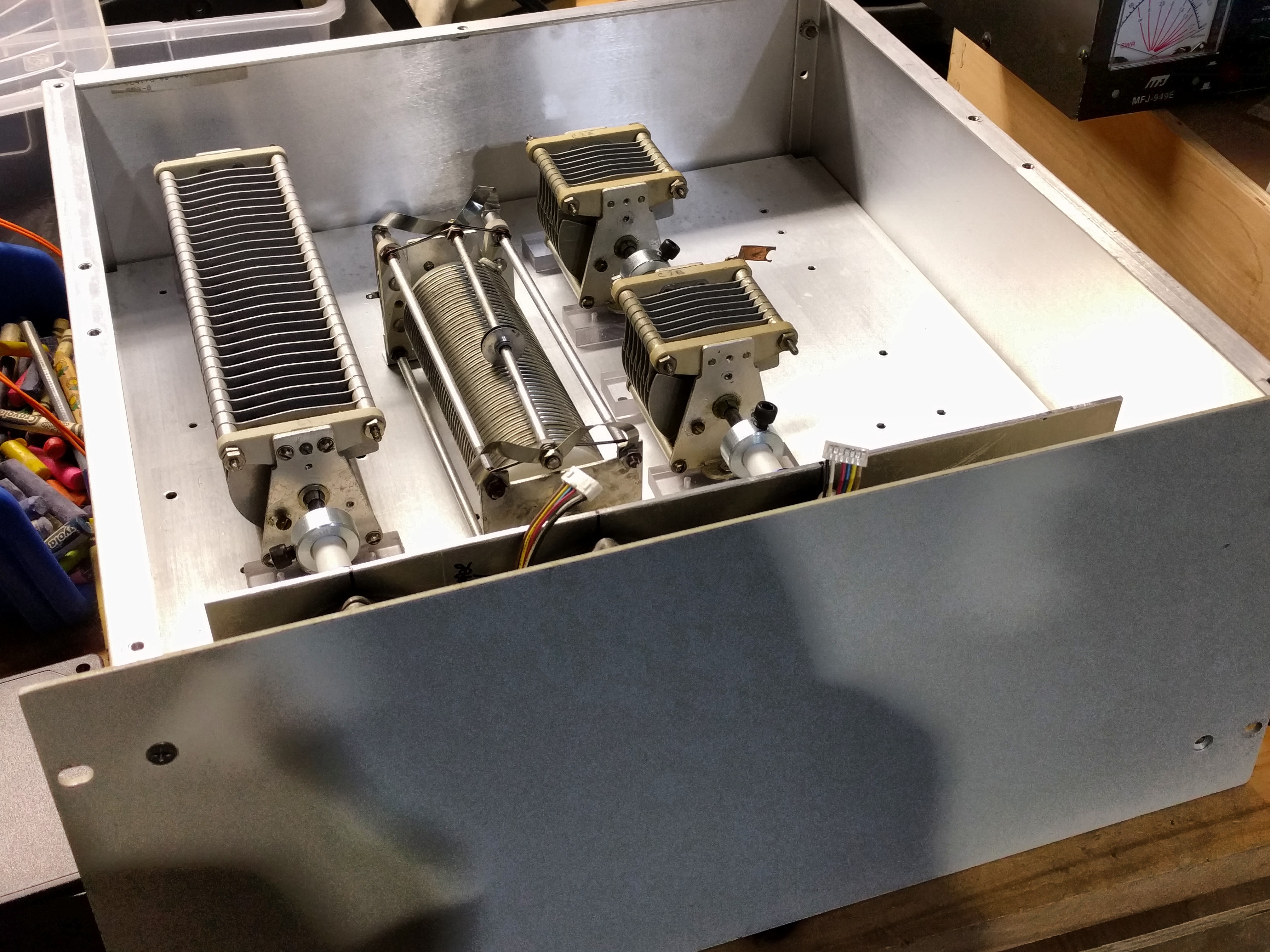
Additionally since my last update I found a cheap 4U enclosure -- which while a bit large -- seems to fit my components much more easily. The enclosure design allows the bottom of the chassis to be re-positioned about 1/3 of the way up -- which will allow for logic and power supply circuitry to be located outside of the enclosure with all of the RF. I imagine the right-hand side to contain the relay crossbar for the 2 x 3 (?) input/output matrix. (Maybe 3x5 -- don't know)
I found some 1/2 inch teflon rod and a 1/4" to 5mm flex shaft adapter for the stepper motor on the roller inductor as well. The servo side of the roller inductor is at ground potential, but the ends of the capacitors have potentially high voltage. I put the teflon rod in my lathe, centered it in a 3-jaw chuck and eased a 1/4" drill bit in the end for the capacitor. A 1/2" collar with set screw seems to do a fine job of holding the capacitor shaft securely.
October 2017
Added my most recent code to github:
I think I'm at the point where I can start reasonably screwing down hardware, installing the arduino hardware in the chassis and testing stepper code.
This page last modified Fri Oct 6 23:13:11 CDT 2017 by timc!