My wife and I have been working on modifying our kitchen for the last several years. In 2006 she bought me a book for Christmas -- how to make kitchen cabinets. In 2007 I started acquiring woodworking tools and I replaced everything in 2008.
The first pass replaced everything but the island. That had to go, but we didn't know what was replacing it. Other intervening summer projects came and went and plans, both small and over-the-top, did the same. Last summer we decided on something completely different and I started making cabinets.
Instead of an island we opted to wrap-around the kitchen into a "G". That left two blind corners which are almost always a waste of space. One of the blind corners opened into the living room with adjustable shelving to hold books, kids' games and such.
The second blind corner presented a bit of a challenge, so I designed a lift.
This is a video of an initial version of the cabinet lift. The control box is required to start the lift and an oversight in the firmware stops the lifting action immediately as the cabinet is resting on the lower limit switch.
Internally the cabinet is lifted using two half-inch stainless 10TPI ACME- threaded screws, a delrin block and lifting bar underneath the travelling unit. Two full-extension 36" slides on the back of the same provide stability 90 degrees to the lifting screws.
Underneath both jackscrews are connected together via chain drive and also to a drill motor to provide the lifting power.
A standard electric drill was chosen due to pricing and availability. This version uses a disassembled $20 Harbor Fright 18V drill, the gearbox of which was completely rebuilt to actually have lubrication inside. The current version uses a Milwaukee M12 drill and the next version will use a Milwaukee M18 drill motor.
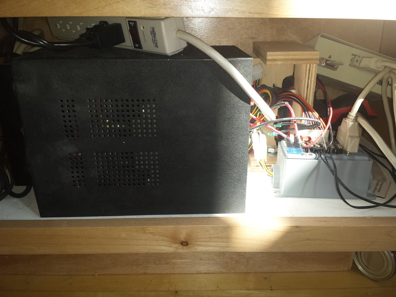
Version one of the controller has an Arduino Mega with a display shield in a small metal box connected via cable to the control box. Initially I had anticipated using stepper motors but NEMA23 steppers didn't have enough torque and I didn't have sufficient room for larger steppers. Visible in the background is the red Milwaukee M12 drill in a jig that holds it tight. The gear that drives everything is clamped in the chuck which passes through the bottom of the cabinet.
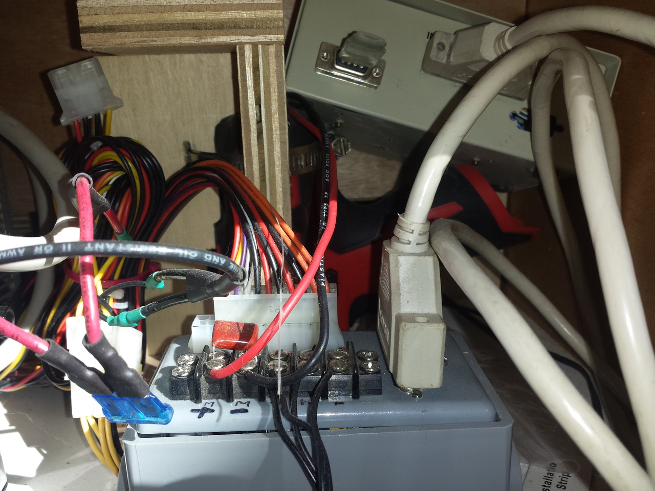
Version one was quickly modified to have a HC-05 bluetooth module that allows it to communicate with an app on our Android phones that remotely controls the lift and lower functionality. The grey control box contains a relay H-bridge. Not fancy but it works.
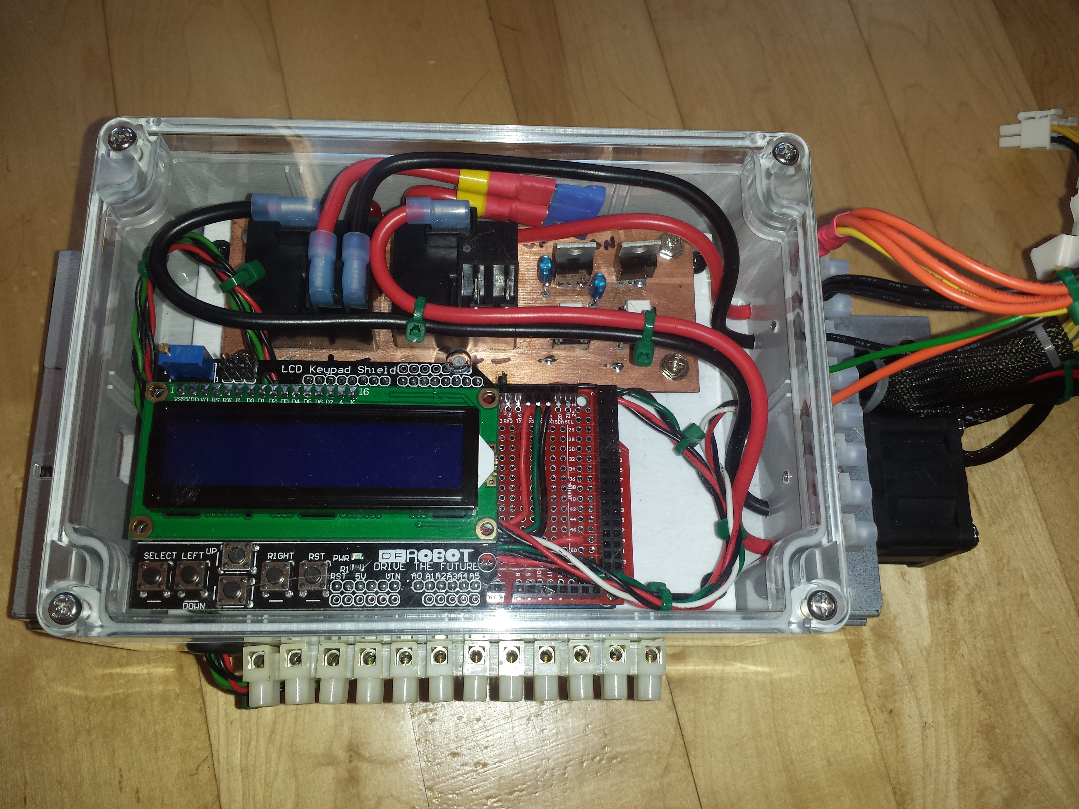
Version two of the controller also uses an Arudino Mega because of the multiple serial ports and interrupt capabilities. The Mega has three serial ports -- one is used for programming/debugging, the second is used by the HC05 bluetooth interface and the third serial port is actually an interrupt line for the lift/lower limit switches. I switched to a interrupt-based limit switch design so that limit switch sense was not subject to any delays in polling.
The upper board in version two has the two high-current relays along with two opto-isolators and switching transistors for the larger relays. Also in this version are LEDs to indicate if a lift or lower isolator has been energized as well as voltage on the lift or lower H-bridge output.
This page last modified Tue Jul 26 12:30:23 CDT 2016 by timc!