It finally happened. I joined the FT-817 "blown finals club". I've had the radio for a while, I've used it with some marginal antennas. And on top of it, I haven't used it too much for transmitting; I have no idea when I joined the club.
Unfortunately I found out that I had joined when I was on vacation in Canada, on an island in Lake of the Woods with a day to kill. I had my vertical antenna about 2' from the water's edge, miles of open water in front of me for about 270 degrees.
And if that's not enough, 20M was open and various locales in Europe were pretty loud. I couldn't contact anyone, even on CW.
I was able to measure the lack of output at home -- about 30mW maximum power on CW was all it would do. That also precluded using this radio with my 222 transverter during the last VHF contest. Bummer.
There are other pages out there about the blown finals. For more information, start here:
Replacing the final board in your FT-817
There are two different final output transistors in the FT-817. Safe to say there are the "newer" ones and the "older" ones. The older ones are no longer in production, I guess. You can still order the MOSFET itself from rfparts.com. I opted to replace the entire board so that I have a spare on which I can replace the MOSFETs if I'd like a spare later. And the complete new board is only somewhat more expensive than just buying a new pair of MOSFETs.
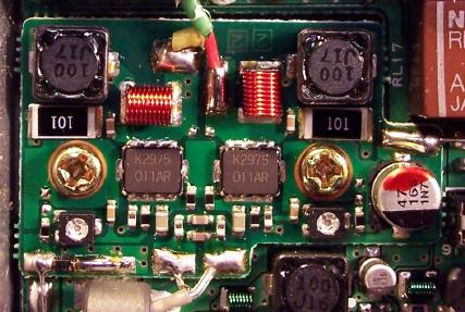
The "old" board.
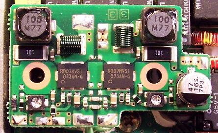
The "new" board, not yet installed.
The boards look similar but a few parts are different. I'd like to later figure out which parts so that I might be able to update my 'old' board to use the 'new' parts.
How do you get the board? Call Yaesu's parts department. 714-827-7600 x6800 as of when I write this. The part you want to order is CB1333001.
I'll have more info (like exact prices and stuff) when I get around to actually installing this in my radio.
Thu Nov 1 11:02:53 CDT 2007
I installed the board in my radio last night. I tweaked the two potentiometers for a total of 70mA idling current. My wattmeter claims now a maximum of 3.5W output. I don't know if I quite believe that number, but it's for sure higher than the original 30mW.
Installation was straightforward. Remove old board, install new board. Use no more heatsink goo than absolutely necessary. Tweak the trim pots to about 35mA idling current each. Button it up and call it good.
This page last modified Thu Nov 1 11:06:52 CDT 2007 by timc!