|
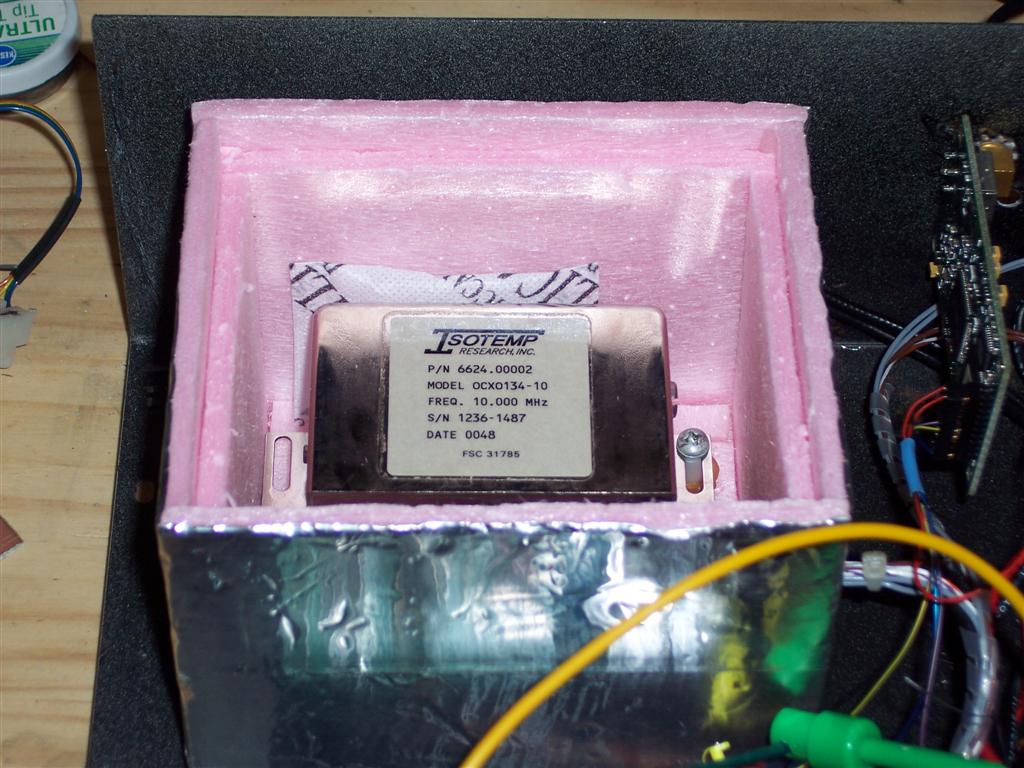
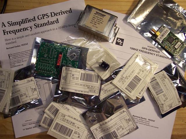
In the September/October 2006 Issue of QEX features a manuscript by Bertrand Zauhar, VE2ZAZ titled A Simplified GPS-Derived 10MHz Frequency Standard. The design makes a lot of sense to me, and satisfies my need (OK, maybe not so much a need, but "hey wouldn't that be cool!" want) for an accurate 10MHz reference for my HP 5345A counters. A GPS-disciplined oscillator is just that -- an ovenized crystal oscillator (10MHz in this case) that is adjusted to be as close to 10MHz as possible by comparing it to the 1 pulse-per-second output from a GPS receiver. This design uses a PIC microprocessor to count the 10MHz pulses over a GPS-timed period and make the oven voltage adjustment from there. VE2ZAZ claims that this project should be able to be completed for under $200 with a well-stocked junkbox. So far so good; my junkbox has two Axiom Sandpiper II GPS boards with 1-pps output, along with some level converters, sockets, etc. I bought a 10MHz Isotemp OCXO134-10 from seller pyrojoseph on eBay. It was either that or a HP 10811...which would have definitely been used and at least 10-20 years old. Needs also a negative voltage in there somewhere I think. Sure, it would have plugged right in on my counters, but that means this project might never get done. The commercially-etched board and pre-programmed PIC were sourced directly from VE2ZAZ. I was originally going to etch my own board, but when I found out how much he was asking for both -- there's absolutely no way I could justify the time to etch a board and program a PIC series (that I haven't used yet) for the price. Beyond the 10MHz output, I also want to use the second NMEA output from the Axiom board to display GPS time on the front of my unit as well. I don't know what method I'll use for that -- 7-segment LEDs, discrete LEDs, a LCD display...maybe nixie tubes? (nixie tubes are neat...) This isn't part of the VE2ZAZ project, but it'll be cool, just the same. Maybe I can further interface that to one of the new microcontrollers with a built-in ethernet interface and have my own personal stratum-II network time reference in the house.
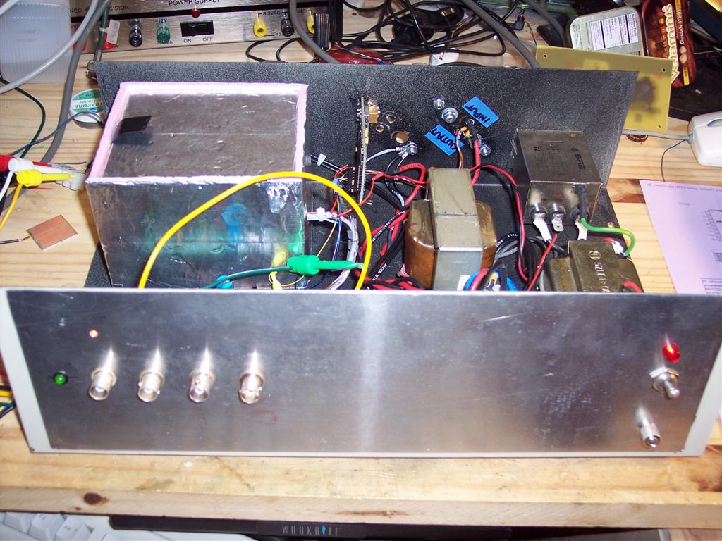
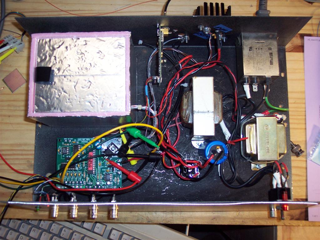
Wed Oct 4 2006 Spent some quality time in the workshop in the last few days. The board went together and was populated in about 90 minutes. Worked quite a bit on how I'm going to enclose this thing. I have a nice steel BUD case in which I built the the "series regulated 4.5 to 25 volt 2.5 amp power supply" which I swear has been in the ARRL handbook for at least 10 years now. This power supply is a piece of junk. Mine worked as per spec. It uses deprecated components. It only goes down to 4.5 volts (gee, I needed 3.5 for a GPS project) is only a positive going supply, has shitty regulation and blows the 723 regulator if you pull too much current when it's on the lower voltage settings. (Is 500mA too much to ask? From this piece of junk, apparently.) I wasted a lot of time fixing and re-working this piece of junk -- should have just bought a commercial imported supply and been done with it. Egads, this thing made me mad every time I looked at it. I needed an enclosure, and that power supply sure wasn't worthy of one. It felt great to open the cover, take the wire cutters, gut it, and toss the parts in the junk box. I'm keeping the power switch, transformer, bridge rectifier and heatsinks. They all worked fine. Those have been re-located in the box to make a nice space for the other PC boards and OCXO. I also built a styrofoam enclosure for the OCXO. Not sure how important this is, but my workshop is in the basement and it gets a little cold down there in the winter. Might as well keep the heat in there a little bit. Put some foil tape on the outside to try and reduce the influence of the regulators and transformers. Will be easy enough to try both with and without the enclosure. Next is wiring up the +12, +5 and +8 supplies. Need to find some tidy way to fuse everything inside. Sun Nov 19 20:54:06 CST 2006 Got the unit operational last week. Not sure what I was thinking. The oven doesn't *need* +8, it supplies +8 to the controller with a pin for feedback between 0 and +8. My daily commute to work takes about an hour. This revealation is just one of many that hit me en-route. Saved me a whole bunch of time.
It works. Got a GPS antenna hooked up outside the house. Unit locks up from a cold start within 10 minutes or so. It's not exactly done yet, I need to wire up a MAX232 to level-convert the PIC from TTL to RS232 and the GPS from RS232 to TTL. (Huh? The Axiom GPS board that I'm using has RS232 out. Fine for monitoring, but I'll need TTL to run to my AVR to get the time out.) Also need to tidy up the wires a bit.
I think the foam igloo for the oven was a good idea -- the shop is running around 55 degrees F in the late fall. The outside of the igloo measured 60.7 degrees and the surface of the OCXO was 102.1 degrees F. Temperatures taken 15 minutes after power-on with a non-contact IR thermometer. If anything, it likely reduces oven current consumption.
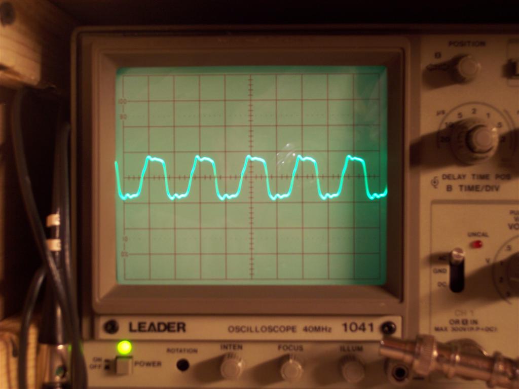
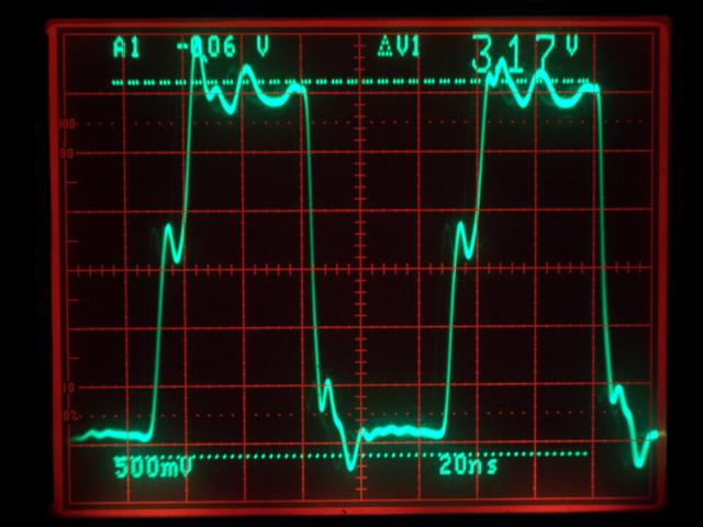
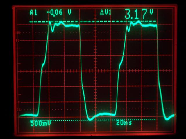
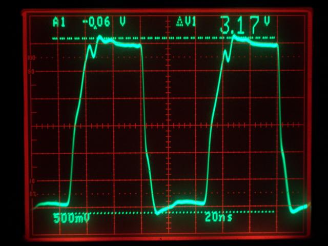
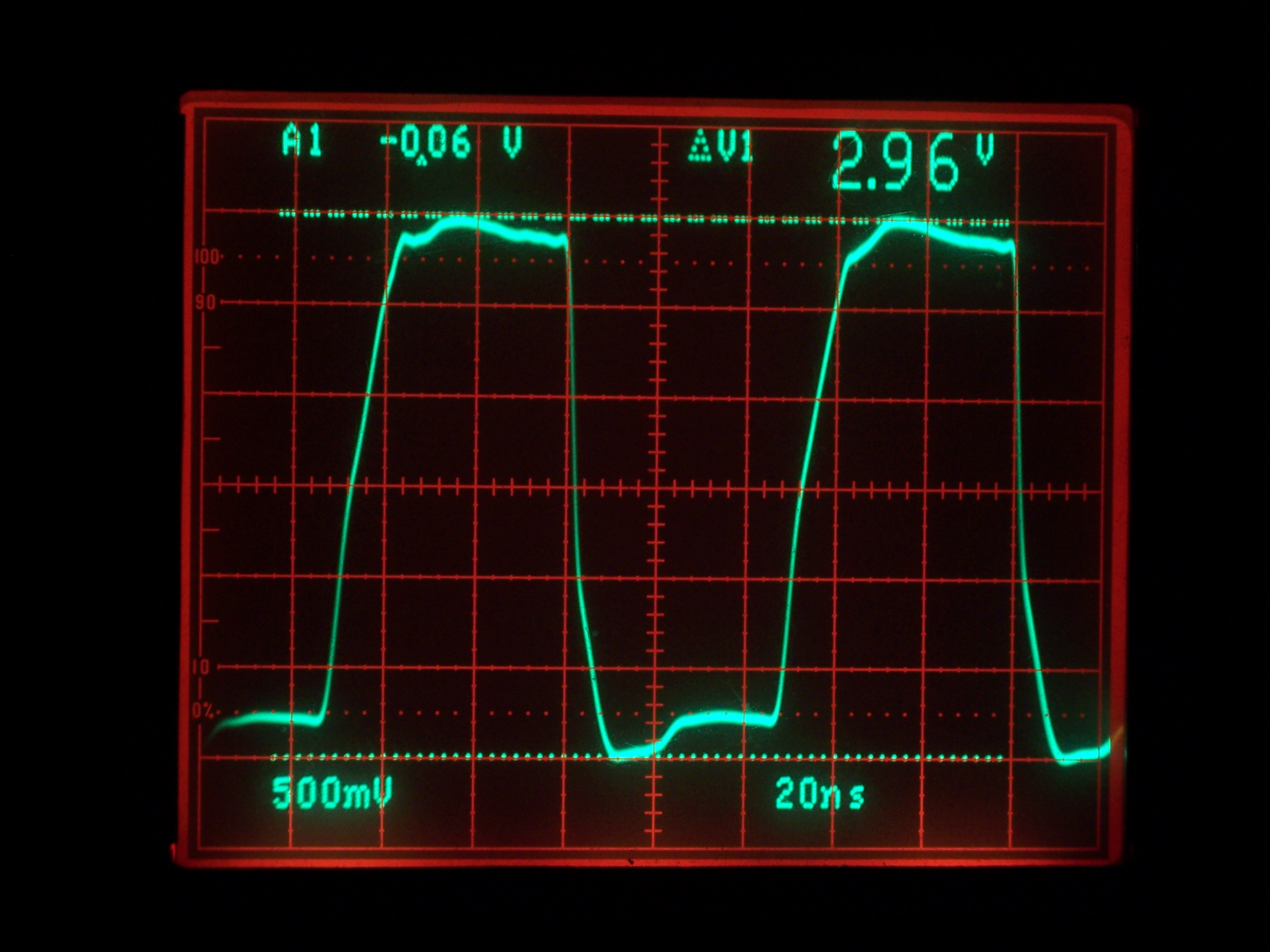
There's a problem with my outputs...the scope says that the output on the board is a nice sine wave at a couple volts. After 6' of 50 (or 75) ohm coax, it's a nasty 10Vpp, almost a square wave, complete with ringing. If I terminate the output with a 50 ohm resistor, it looks a little better.
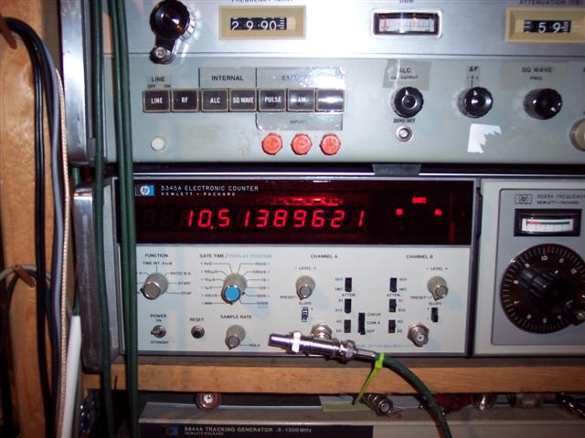
My HP5345A counter (using the internal standard which is close enough) claims it's 10.513 MHz. My cheap handheld counter says 10.00001MHz. The 5345A isn't 513KHz off...I think it's just including that ringing. Or something.
I don't quite understand what's going on here -- a termination issue probably -- but it's safe to say that when I figure it out I'll certainly have learned something.
Tue May 1 09:08:10 CDT 2007 I just blew away a bunch of stuff from November in favor of some better pictures with a little more insight on what's going on here, I think. All measurements done with a 50 ohm terminator on a tee at the scope.
So, the waveform looks a lot better as the outputs of the MC3487 are terminated. It causes the chip to run a lot warmer, but my AD9833 DDS waveform generator (November 2005 QST) uses this my GPSDO as a 10MHz reference and gives some strange results with the strange waveform.
Counter reads 1.0513 MHz while counting the 1MHz signal using the 10MHz signal as a reference, and with the internal oscillator. I'm now very suspicious that my HP 5345A is not working properly.
To do:
Tue May 1 09:31:48 CDT 2007 Yeah, my HP 5345A has a problem. My cheapie counter can recognize the 10MHz signal as 10MHz. My even cheaper voltmeter can count the 1MHz signal.
Mon Feb 11 10:33:35 CST 2008 I still haven't fixed my counter. But I realized that all I need to do is use the 10MHz output from the GPSDO and set the counter to do a B/A ratio using the 10MHz output on the A input. Good enough for now! Sun Mar 2 20:58:07 CST 2008 Long story on the counter, it's now fixed. See the tale of my HP 5345A counters. Also built a 9-section low-pass filter for the counter that I can use on any output. Results in a really nice-looking sine wave at 10MHz. More to come.
This page last modified Sun Mar 2 20:57:59 CST 2008 by timc! |