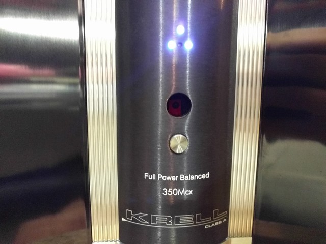
Krell 350Mcx re-cap
The following are my notes for the process of replacing the capacitors in a Krell 350Mcx amplifier. The entire process takes approximately five hours from start to finish. You will need a T-25 Torx drive, 7/64" hex wrenches and a complement of nut drivers. This is not a good beginner project, but should be easy enough for an individual with good soldering skills, mechanical aptitude and an eye for detail. This project does have the potential for disaster, but it's not due to any design shortfall on Krell's part -- the mechanicals are sound, the boards are top-notch and the fit and finish is commensurate with what you'd hope for in a high-end audio amplifier.
The DigiKey BOM is here: http://www.digikey.com/short/q75498 -- the parts list was approximately $160 when I last ordered.
Total time for disassembly, parts replacement and re-assembly is approximately five hours.
Why replace the capacitors? Electrolytic capacitors have a finite lifetime and degrade in the presence of heat. This class-A audio amp gets hot. Some of the original capacitors are both Nichicon and Jamicon, this is a replacement with Nichicon and Vishay parts.
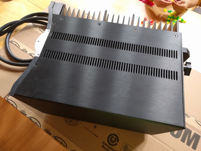
It's easiest to work in an area with enough room to separate the heavy components. Disassembly will take about 30 minutes.
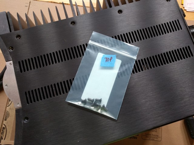
I would very strongly suggest bagging all of the screws removed from the various assemblies in multiple bags -- one per side works for me. Note that some screws are differing lengths, making notes of which screw goes where is a good idea.
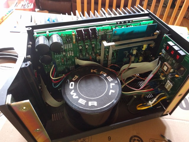
Once the top is removed, there are internal interconnect cables that will need to be removed. Make note of the orientation of the cables, as it is different between the two models of this amplifier, and there is no immediate indication of cable orientation on the board.
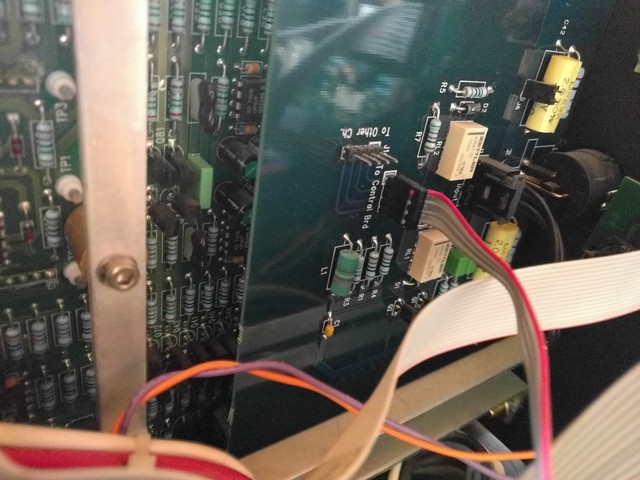
Remove the 4-pin cable from the input board, note the connector to which it is attached and the orientation. There are two film caps on the input board, but I didn't bother with these, as they are shorted out in the configuration in which this amplifier is used.

There is another cable on the regulator board. Red down on this model -- red up on the other. Make a note!
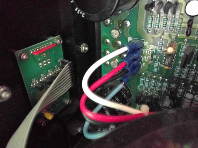
Remove the four power input cables from the regulator board and the cable from the front display board. On this unit, the QC terminals removed very easily. I made a note of that.
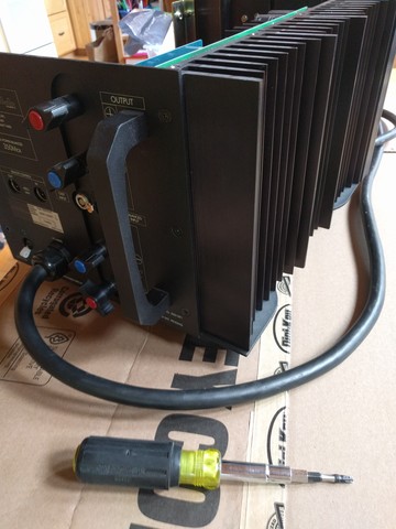
You can now remove the circuitry from the chassis. Start by removing the three screws on the back. This will separate the power control board from the heatsinks. My preference for disassembly is to insert a T-25 Torx bit designed for cordless screwdriver into a good "11-in-1" screwdriver handle. This allows for plenty of torque for disassembly and good feel on reassembly. The heatsinks are aluminum and the screws short and fine pitch. A gorilla could easily strip this. Don't be that gorilla.
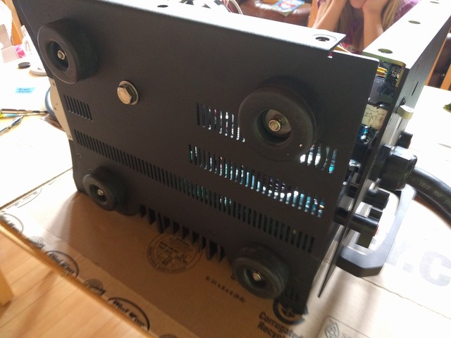
Carefully remove the six Torx screws from the bottom, this holds the chassis to the heatsink. Note that the chassis is quite heavy with the attached transformer. Perhaps twenty-five pounds? Support the chassis with one hand while removing the screws, or get assistance to prevent unexpected shifting during disassembly.
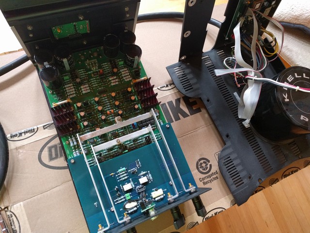
The chassis will now easily separate from the heatsink and electronics assembly. This is also a heavy assembly, but it can rest safely flat on your workbench.
Remove the four nuts from the output posts, the two hex screws and brass standoffs from the aluminum output straps.
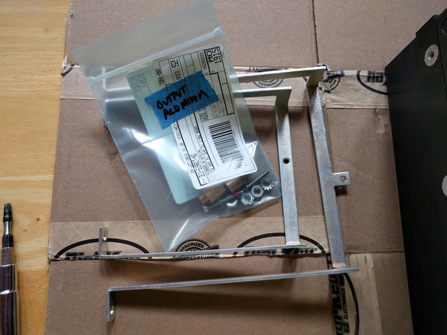
I think there's room for aftermarket improvement with the amplifier here -- silver plated copper or similar instead of aluminum?
Remove the three remaining hex screws holding the input/output board to the chassis.
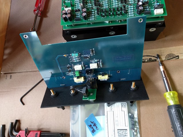
To remove the input/output board, remove the four hex screws and carefully pull up. There are multiple 0.1" spacing pins between this board and the regulator board. Caution, the aluminum back plate and the blue PC board are attached only by an XLR connector that you can't remove without desoldering. Since you won't need to touch this again until re-assembly, just carefully set it aside.
You're now left with the regulator board. There are several stand-offs, hex screws and two machine screws connecting this to the amplifier board. Make note of which locations have stand-offs and which locations have hex screws.
These are the two machine screws holding the full-wave bridge rectifiers to the heatsink. Be sure to also capture the lock washers and hold those back as well.
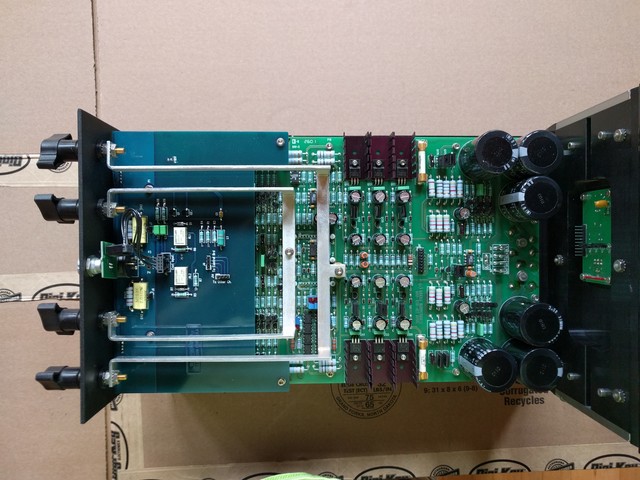
You will be replacing all electrolytic capacitors on the regulator board. To ensure that I have all capacitors done, I like to take a sharpie and put a dot on each of the existing caps. I like to desolder all of the same value capacitors at the same time. I use a powered solder vacuum for ease in removal and replacement. This is also done while standing, having mounte this board vertically in a large PanaVise 315 PC board holder.
Replace the capacitors, clip the leads. Note the polarity of the removed capacitors and ensure that you are removing the value that you are expecting. When in doubt, the square pads are +, the round pads are -. Replacing all of the capacitors on the regulator board takes about two hours.
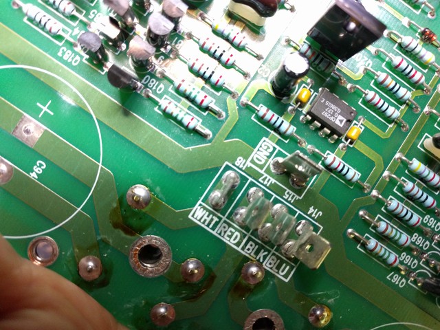
While you have the board out, inspect. On this board, the input flag terminals seem to have been bent at some point and I see cracked solder joints. I touched these up prior to re-assembly and also tweaked the quick-connect terminals ever so slightly with a pair of pliers to make them connect tighter. Whoever was last in the amplifier also left some unnecessary flux residue behind; this was also cleaned up.
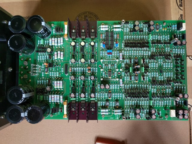
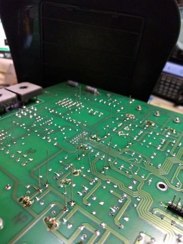
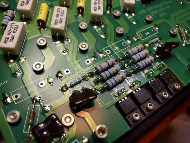
There are 28 47uF 100V capacitors on the amplifier board. Note the polarity and remove all of the capacitors. I like to desolder each end and then clean the holes with a solder vacuum.
There are also four film capacitors on the board. Replace these as well.
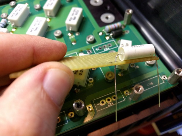
The installation of parts on this board is done from the top. As such, the leads should be pre-formed and clipped uniformly to length prior to installation. I use a simple jig made from a piece of perfboard to pre-form and clip the leads of the capacitors prior to installation.
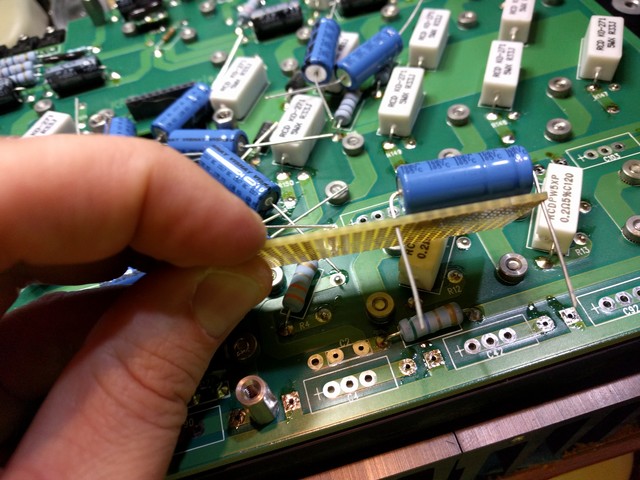
I like to ensure that all of the electrolytic capacitors on this board are bent in the same direction with the value and polarity marked so that it's visible on the top.
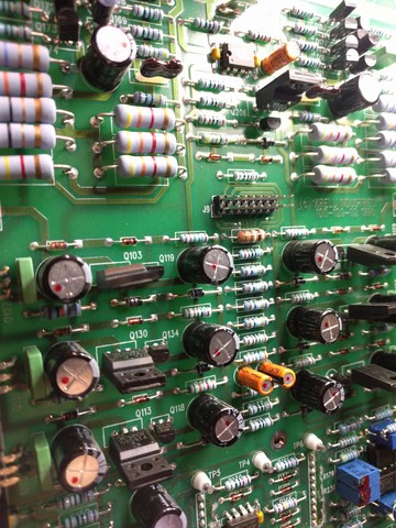
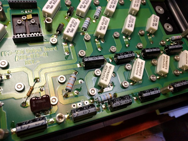
Half of the capacitors replaced. Note the uniform orientation of the capacitor body.
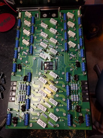
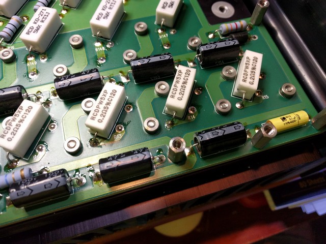
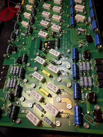
All capacitors replaced. This takes about an hour.
When done, re-mate the boards. Make careful note about the orientation of the intra-board pins and that they are all socketed.
Do not re-attach the heatsink to the chassis, you have a few more capacitors to go on the control board.
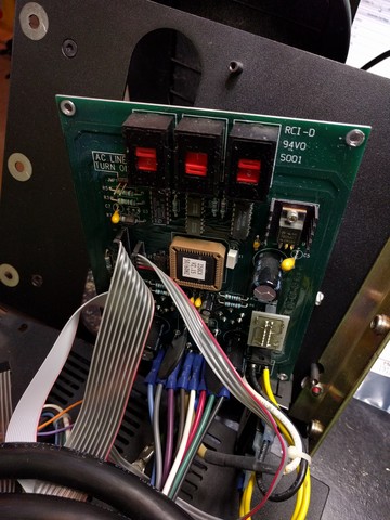
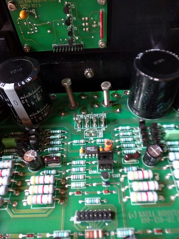
This board is the hardest to change as it's stuck to the chassis wiring. There are only six (IIRC) caps on this board, so it'll be fine.
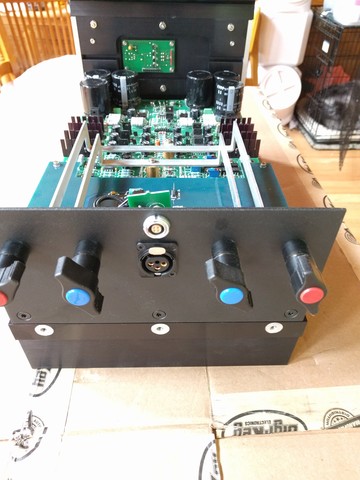
Simply re-asemble what you took apart. At this point you will be thankful to have individually bagged all of the screws. Also, re-connect the wiring. When done, test.
last modified Sun Oct 8 18:27:34 CDT 2017 by timc!