I don't recall where I first saw this project but I knew I had to build it when I saw it tied together home environmental monitoring along with a Raspberry Pi. The PiAQ is developed by the National Association of REALTORS' CRT Labs.
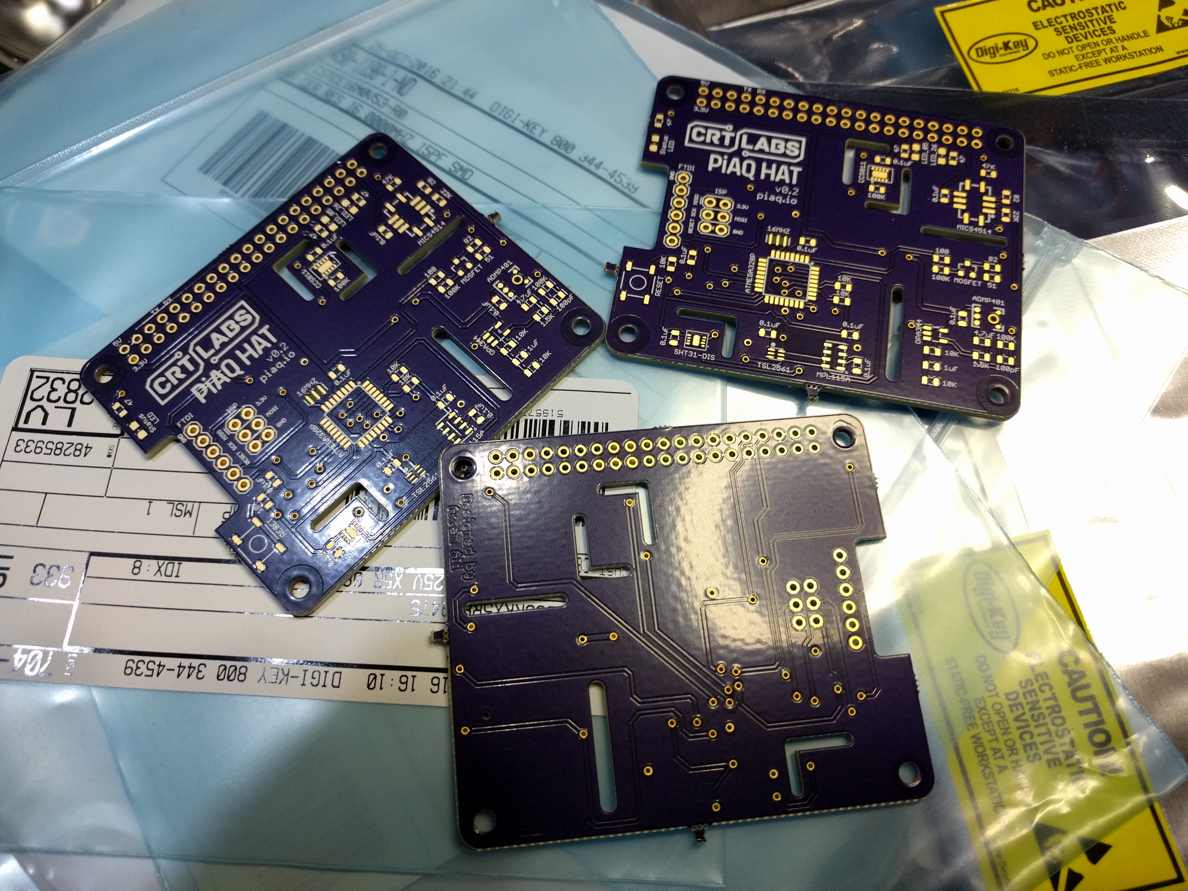
The boards are available from OSH Park which is a PC board aggregator/manufacturer/all-around benefit to the experimenter community. For just a few dollars and a week's wait I got three perfect purple gold plate board for this project in addition to boards for another project and a teensy 3.2 USB development board with 32-bit ARM processor for a good price.
Step one: get everything together. I spent a minimum of time ordering parts, the piaq webpage pointed me towards a BOM on octopart.com and I was able to import that complete order to DigiKey in just a few clicks. I might be short a sensor from a different vendor but whatever.
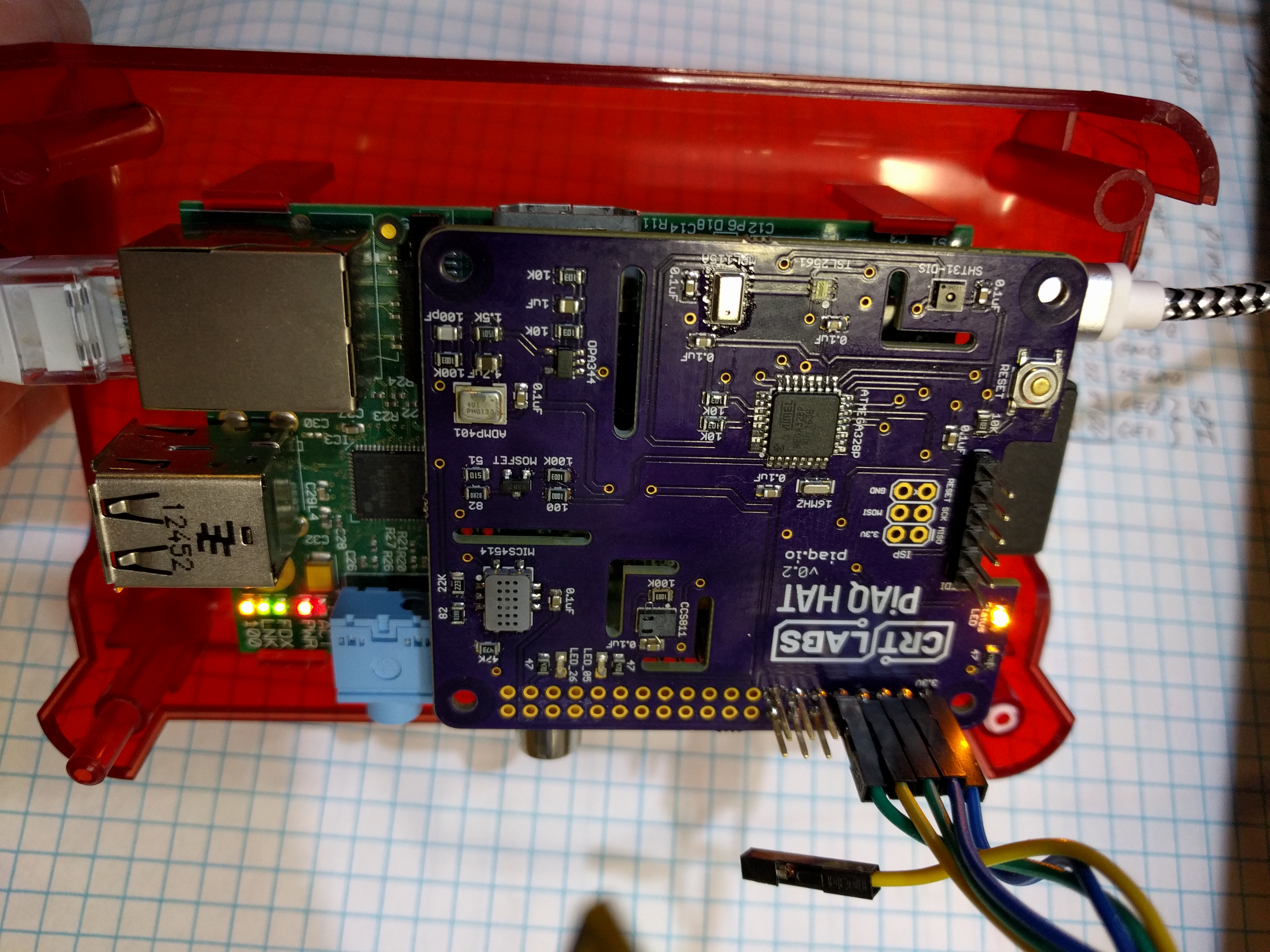
The project appears to be using an AVR processor on a board that attaches to the Raspberry Pi GPIO header -- it has an arduino bootloader, is programmable via the wiring/arduino environment and gives data back via serial? That's a fascinating way to do this! An arduino as an, if you will, co-processor on the rPi. In my mind that will also simplify any testing as I won't need to always be connected to the rPi for testing during building. The inputs on the ATMega are way more tolerant of crap than those GPIO pins on the ARM chip.
Next step: populate the board just enough to get the ATMega328p ready to install a bootloader.
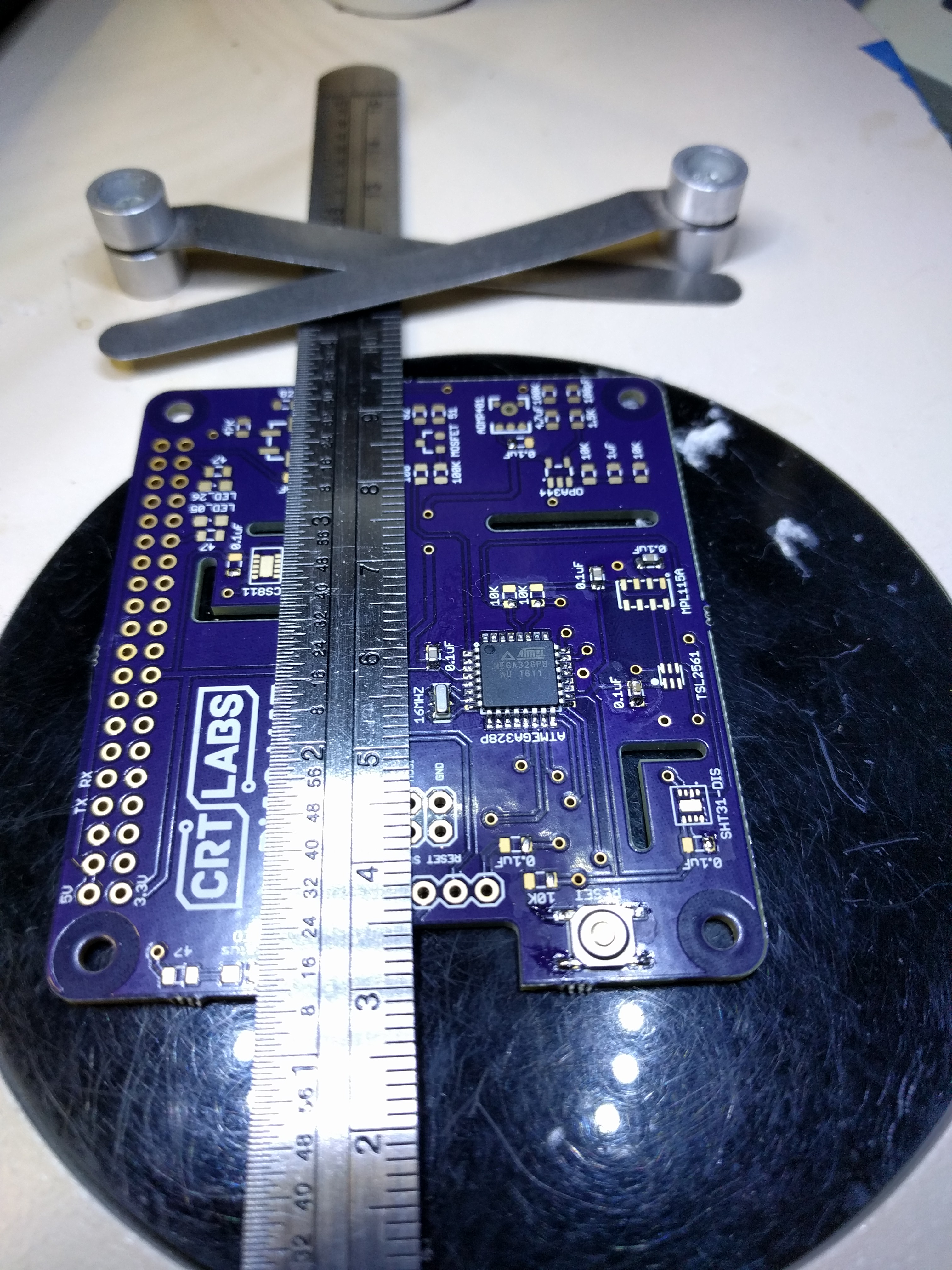
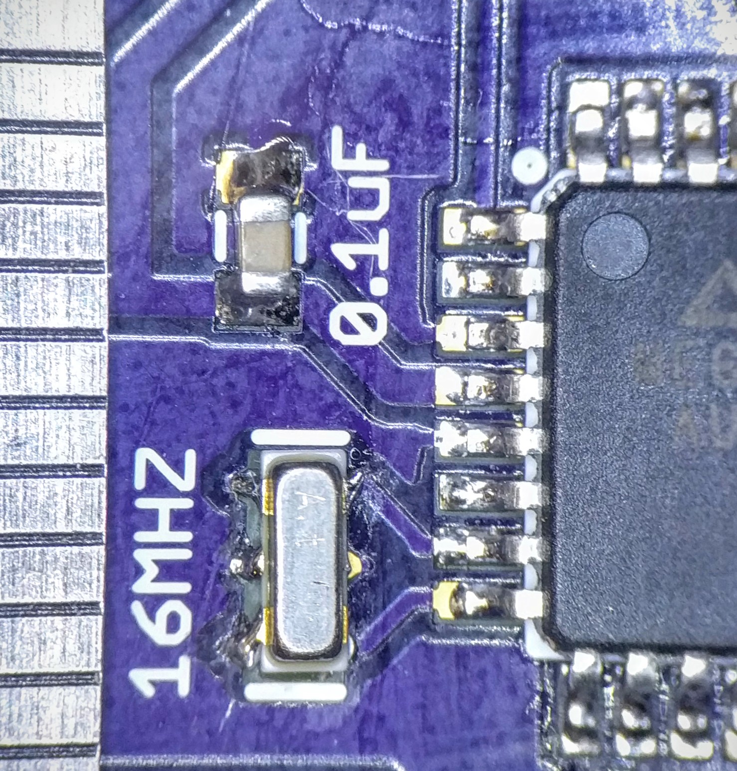
It took just a few minutes to solder down the ATMega. There's a little bit of re-learning a technique here. The solder joints on the first side were a little uneven but by the time I reached the last side everything was reasonably uniform for application of solder. I don't have any sort of reflow oven so it's all by-hand for me.
Although not strictly necessary for programming the AVR, I populated all of the 0805 0.1uF caps on the board at the same time along with all of the 10k resistors. I'll avoid populating any other components so that I don't restrict access unnecessarily to any of the other on-board devices for the purposes of soldering. I use an older MX-series Metcal rework station and 10x stereo magnifier for everything.
Next project is to program another arduino board temporarily to flash a bootloader on this AVR...and then flash the code on this chip.
Wed Nov 16 22:26:50 CST 2016
Little bit of a setback -- apparently if you just populate the DigiKey BOM from Octopart you get an ATMega328PB, not an ATMega328P...so watch that one. Supposedly pin-compatible but the bootloader is different.
It does look like someone has some support for that -- so I'm going to go with it and see what happens. I'm really not excited about de-soldering that chip from my board.
So...it looks like I can put a bootloader on the chip but the rest of everything else is half-baked for wire.h support on the new chip -- for the cost of buying a new $3.50 chip it's not worth the bother of debugging this one.
Sun Nov 27 23:25:32 CST 2016
I ordered some ATMega328P chips from DigiKey and managed to get a bootloader flashed using another Arduino Uno board I had on-hand...and yeah, ended up desoldering the '328PB. Once I had the requisite libraries installed in the arduino environment everything compiled and programmed to the board without a problem.
Time for a few sensors. I started with the MPL115A pressure sensor. I ended up modifying their provided code as it assumed an MPL3115A sensor. Also on board are the TSL2561 (light), SHT31 (temp, humidity) and ADMP401 (sound). I'm not averse to small parts, but damn, these are small. With exposed pad I can mostly flow under using the smallest tip on my metcal - but the ADMP401 leaves no exposed pads at all. So, time for backwoods hot air techniques. I tinned the board pads, wrapped the board in aluminum foil leaving only the area of interest exposed, applied no-clean flux set the part atop and hit it with my heat gun. At the count of five the part settled down nicely. When I build the next two boards I'm really going to have to do this for all of the parts or acquire a hot-air system before then.
Everything is showing a value. Values for the MPL115 are a little goofy and the numbers for the ADMP401 don't change much. I still need to acquire the MICS4514 (CO/NO2) and CCS811 (CO2/VOC) sensors -- but this is something I can work with.
---------------------
Sound Level: 505
Light intensity (lux): 432
Vnox: 511 Vred: 505
CO concentration (ppb): 131.55
NO2 concentration (ppb): 156.03
MPL115A2 Pressure(kPa): 309.7104
MPL115A2 Temp(C): -73.13
MPL3115A2 Altimeter setting InHg: 0.15
SHT31 Temperature: 21.07
SHT31 Humidity: 46.02
No Status, check IAQ Core
CO2 concentration:65535
IAQ core Resistance: -1
TVoC concentration: 65535
At this point I'm thinking I really don't need to attach this to an rPi -- the unit just has serial out. I'll probably use an ESP8266 and maybe display the data on a status webpage and/or with some serial out.
Sat Dec 3 00:14:13 CST 2016
I purchased a cheap offshore hot air rework station earlier this week. It arrived today. I was able to solder down the ATMega328P on the other two boards along with support components in short order. They're now all flashed with a bootloader and my test program is uploaded. Maybe I'll populate the rest of the boards this weekend.
Sat Apr 8 22:24:58 CDT 2017
More progress. I have since gone to using MPL3115A2 pressure sensor instead of the MPL115A that I never could get to work. Same form factor -- but it works. I don't know what was up with the other things.
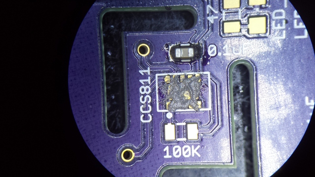
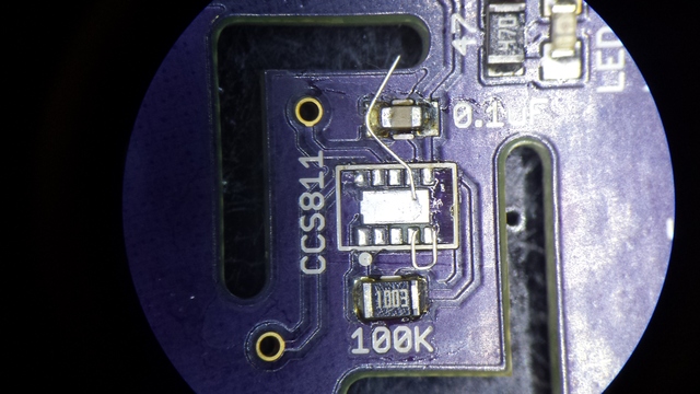
Found a problem on the v0.2 board. I acquired some CCS811 air quality sensors (CO2 and VOCs), soldered them down and couldn't find anything at their I2C address. Turns out you need to minimally tie pins 4,5 and short 7 to ground. None of this was accomplished on the board. It's quite the small part so I thought about it for a week. I ended up using a single strand of wire from a 24ga bundle (0.006") on the board, soldering that down and adding a bit more solder and reflowing. It worked! Not the prettiest and not all pads touch but the pins that I need are attached and the sensor displays values when I either blow on it or give it a whiff of IPA.
I'm really going to have to pay attention to what was done with the board for the MICS4514.
The following are the steps I used to prep for my hack wiring job, I wouldn't normally have to reflow with paste before placing a part.
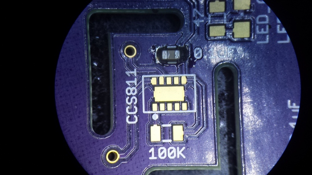
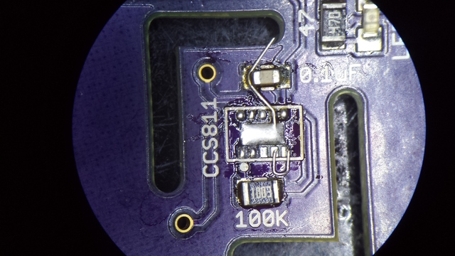
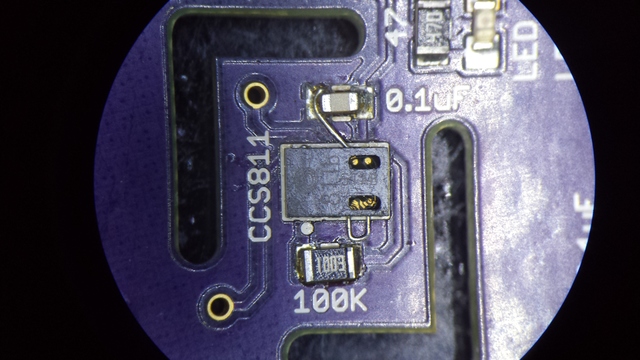
Example of part being soldered using my hot air rework station. It usually doesn't take this long but it's a little hard to hold my phone to the microscope, hold the board and hot air handpiece all at the same time as inspecting the process.
Mon May 22 23:25:05 CDT 2017
I can't believe I kinda finished something.
The MICS-4514 devices arrived last week and I took the day off for my birthday. I cobbled together some Arduino code to read all of the sensors -- the CCS811, MICS4514, MPL3115A2, TSL2561 and SHT31. The CRT Labs stuff in githubt didn't quite meet my needs. Data is presented to be read by a python script on my old Raspberry Pi and then stuffed over the network into graphite.
There's a weird problem where the PiAQ hat won't initialize when connected to the RPi, so I'll make some sort of simple reset circuit using a GPIO pin and a transistor or something like that.
One concern with this setup is that the devices that register temperature are in close proximity to a Pi that runs pretty hot. I do have another device (DHT22) that's within a few feet of this device. Maybe some sort of insulation between the boards? A cable?
This page last modified Mon May 22 23:24:59 CDT 2017 by timc!