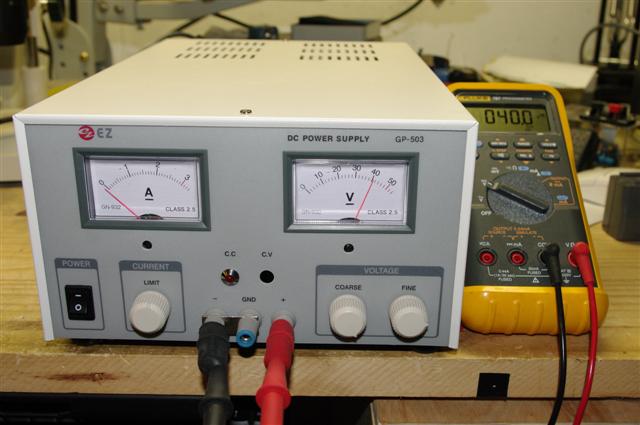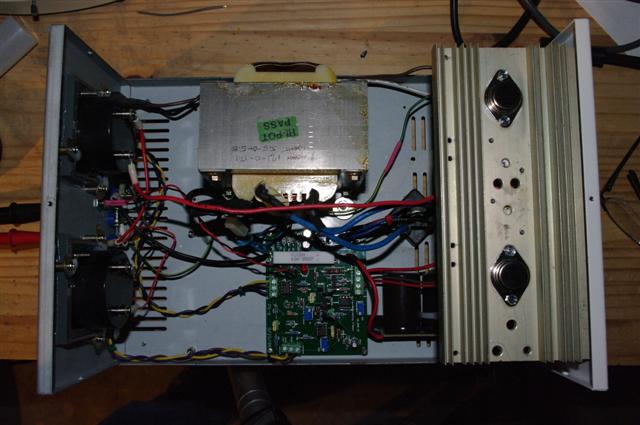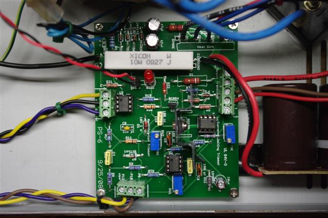
A year or so ago, I picked up this great variable power supply carcass at a local hamfest. A bunch of people wanted to know how much I paid. "Five bucks!" -- they were all impressed. 'Course, I don't think they realized it was mostly empty inside.
And recently I ran into this project:
0-30Vdc power supply at electronics-lab.com
But what you find when you visit the forums for this project is almost 3000 posts refining the design that really didn't work the first time around. It looks like they're converging upon a circuit that works properly. I'm pretty sure that's what I'm building.
But that's probably the best thing about the circuit. Question about the choice of a part? Search, and it's likely been discussed. There's more documenation than you can shake a stick at here.
Anyway, I've acquired a very nice PC board from one of the forum members to greatly simplify the project implementation. I spent last weekend selecting and ordering parts from Mouser. They arrived Thursday. I've been working on stuffing the case today.

And I suppose I'd be done by now, but the spare transformer I have puts out a bit much voltage. The filter caps peak up around 53 volts, a little close to their 63V rating for my liking. Maybe I can pull a winding or two off this transformer or order a new one? Or modify the circuit to use the higher input voltage, and just upgrade the caps?
In any case, I think the current plan is to purchase a new transformer with a lower output voltage to get this circuit working properly. THEN I'll consider using an analogous circuit to get a higher output voltage using the larger transformer on a new power supply.
Fri Feb 13 22:31:46 CST 2009
Ahh, Friday the 13th. A great day to work on a power supply. Last time I left this project, I was doubting if I should power it up at all, as my transformer puts out a little more voltage than what might be optimal for this project.
I have been conversing via email with the PC board designer letting him know of my progress. He related that he did a similar build with a rewound transformer that was also a bit high. Even though the opamps aren't rated for the higher voltage -- they worked anyway.
The selected opamps are cheap -- so I put it all together and tried it. It worked, sorta. The maximum output voltage I was seeing was around 10V. So far, so good, but a little low in voltage. I figured it had to be something simple because there wasn't smoke. Just 0-10V.
Another weekend passed and I sent another email to the PCB designer with my progress -- or in this case, the lack thereof. He immediately emailed me back, suggesting that maybe the 10V Zener diode was installed backwards. And half a dozen other things to check.
Bingo. The 10V Zener diode was backwards. Completely my fault. I obviously am incapable of matching up a black band on a diode with a silkscreen picture of the same. So, if I screwed that up, what else did I screw up? Answer: the other Zener diode, too! (I must have something against Zener diodes?) After those two errors were fixed and everything else checked out visually, I applied power again.
Success! A little tweaking of the variable resistors on board, and I can now get 40V out from the power supply. It can go to 50, but I've set the output so it's a 40V max. I will probably lower it down to 30 later, knowing that I can always boost it up to 50 if the need arises.
The only problem so far is that the 10K coarse voltage adjust potentiometer that I selected (I wanted a specific size to fit my chassis) has an audio taper. 0-20 volts is nice and slow. 20-40 zips up pretty quickly. I'll be changing that out soon.
Next up -- installing a pilot light in the empty hole to show that the power's on, selecting a replacement coarse voltage adjust potentiometer with a linear taper and making room on my bench for the new hardware!
All-in-all, a very nicely designed project, that does what it should. I've learned a bit, and I look forward to years of service from the hardware.
This page last modified Fri Feb 13 22:53:43 CST 2009 by timc!
