The speaker was dead. I wasn't able to get a reply from any of the Tannoy authorized repair centers for a replacement board. I wasn't interested in packing up and shipping a relatively large speaker for a repair that could cost more than replacement...hmmm. I had another set of speakers that I was using in place of the Tannoys...so the repair fell down the list for a while.
The Tannoy Reveal 6D speakers do sound really nice. Plus broken things bother me especially when the fix is so obvious. My plan was to etch a new board to repair the speaker. In November 2011 I stripped the problem board, made an inventory of components, and started down the long path of making another board.
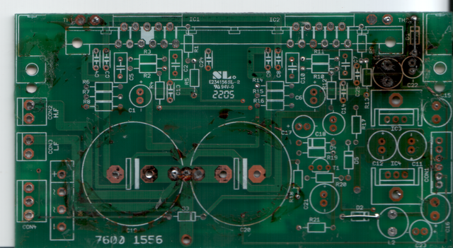

You can see the damage done to the board by the power resistor.
With the boards stripped I tried making scans with my scanner. However the residual solder blobs and jumpers kept the board above the glass and resulted in a suboptimal scan. The next best thing was a raw image from my DSLR.
A picture of a green-on-green board with charring and silkscreen was what I had to work with. No amount of photoshop level magic resulted in a clean or useable black-and-white image that I could etch from. Editing the image by hand was going to be some tedious work. The project sat for a couple years.
Skip ahead to November 2013. A mostly random google search for this speaker resulted in a schematic of the board in question! I had one that I drew up, but a factory one is even better! I remember I looked a few years back but didn't find anything. Having cleared my workbench just days earlier, this project once again came to the top of the list.
The Tannoy Reveal 6D uses a pair of LM3886 class-AB 68W audio power amplifier chips, one to drive the low-frequency speaker, one to drive the high-frequency speaker. The board in question functions both as a power supply for the amplifier chips and other circuitry in the powered monitor.
I briefly considered using some other commonly-available LM3886 amplifier boards along with separate power supply boards to replace the functionality. While that was tempting, I decided at best that would be a complete hack and opted instead to do the work and etch a duplicate.
I had an evening in November 2013 where I decided to just do it the hard way and clean the image manually. Using GIMP -- a photoshop work-alike -- on my laptop I manually cleaned all of the lines and produced a black and white image of the front and back of the board.


With that I was able to use the toner transfer method to get some etch resist (toner) down on a circuit board. It wasn't perfect and I had to go over most of the board with a sharpie to ensure good etching. But I had something to work with!


I etched the board and got a reasonable fascimilie of the original. There are no vias and the front/back registration isn't 100% perfect but it's good enough.
Fortunately after stripping the board in 2011 I went ahead and ordered all of the replacement parts -- the Mouser packing list is dated December 2011. Newly-etched board in hand, I was ready to stuff the board. I started with the power supply section first. I had to be careful with drilling and watching the vias. Some of the traces were a little tight and I had to be sure to place c-wires in the right spots. After one missed via, the power supply section tested just fine. +/-40VDC for the amps and +/-15VDC for the other two input boards.


I had to re-use the original 10000uF 50V caps because my replacements were just a bit too tall. The ESR measured OK so that's fine. The rest of the parts were new Nichicon or Wima capacitors and Xicon 1% resistors. Looks like I also re-used the bridge rectifier, but whatever. It tested fine, too.
And that's where I stopped, just prior to going to bed for the evening.
Mon Dec 2 22:28:36 CST 2013
Smoke test. Well, no smoke but something stinks. The 5W 120 ohm resistor in series with the +15V regulator is getting really hot when plugged into the input board. Hot like +190F as measured with the IR thermometer! The heatsinks on the regulators were plenty hot too. Without a load the power supply/amp board doesn't get hot.
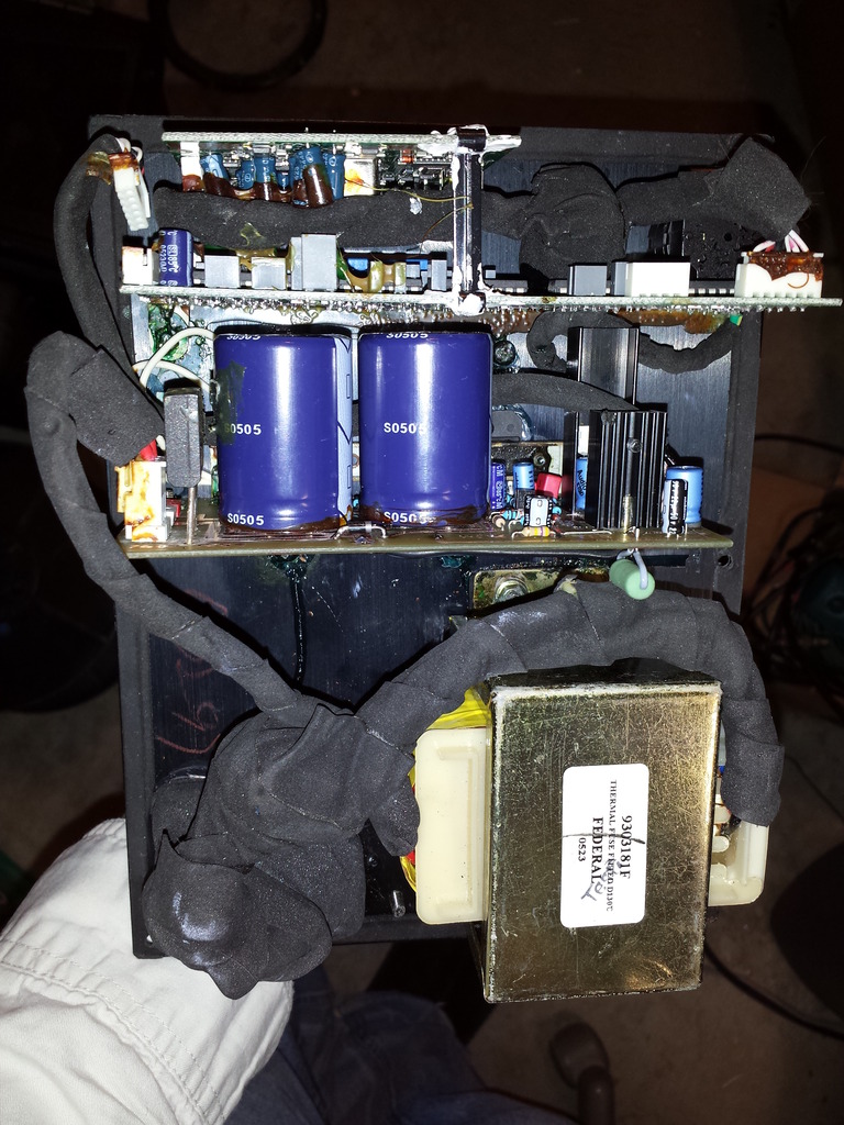
Next up, try again without the digital board. Then troubleshoot the audio input board. Consists of five LM837N, one LM833 and a bunch of caps. And a bunch of brown goop. Brown goopy glue all over the place.
Tue Dec 3 23:00:00 CST 2013
Audio input board and digital board removed. Brown glue mostly removed -- 10x magnification and dental pick. ESR on the small input caps on both boards looks OK, no obvious shorts. Trying with only the input board, no audio out and the -15V resistor and heatsink start warming quickly (+105F/40C) while the -15V regulator rises only slightly above room temperature. Voltage looks good however. Next two things to try -- try shorting the mute circuitry and run without the input board, make sure my newly-etched board works at all. Then try a separate +/-15 supply on the input board and digital boards and verify the current consumption isn't out of line.
Fri Dec 6 00:05:00 CST 2013
More testing. Previously no sound from the speaker. Decided to go over the board I made very carefully looking for mistakes or (more likley) missing vias. After an hour or so I found two missing vias on bypass capacitors at the +/-40V rails. No voltage was reaching the amp chips. Now back to trying to determine if there's a problem with excess current consumption on the input board.
Sat Dec 7 01:23:58 CST 2013
Success! I'm listening to the speaker as I type. Testing on the audio board shows a consumption of around 60mA on the + and - 15V rails. (Still need to test the digital board) -- but of concern, L2, the 220 ohm 5W resistor is getting warm -- +109F at the moment, whereas L1, the 120 ohm resistor is stabilized at +70F.
Sat Dec 7 19:43:51 CST 2013
More numbers: The 120 ohm resistor before the LM7815 has a 7.3v drop, from 39.5 to 32.2 before the regulator. Power dissipation of 0.44W.
The 220 ohm resistor before the LM7915 has a 14v drop, from 39.5 to 25.2v, 0.9W dissipation. This resistor gets too hot.
Currently running without the digital board. It pulls almost 1A on the 15V line and then drops to 33mA. Regulator gets pretty damn hot. I think there's an issue here (that I can live without for the time being...). The ESR on the cap on the output of the regulator was 1.2 ohms...new Panasonic 100uF 10V cap was 0.42 ohms. I think I'm going to replace them all and see what happens.
And I think I'm going to get some chassis mount power resistors for L1 and L2 and be proactive about this failure mode in both units.
Sat Dec 14 18:50:55 CST 2013
Done. The 30 watt chassis-mount power resistors arrived from Digikey on Friday. I drilled and tapped two 4-40 holes in the middle of the chassis through the heatsink and mounted the 120 and 220 ohm voltage dropping resistors on the inside of the back panel. I did this for both the newly-repaired speaker and the speaker that didn't (yet) have a problem.

The temperature of the power resistors doesn't increase noticeably during operation. DAC disconnected on both units. New capacitors didn't help the non-functioning unit, and I didn't use it anyway.
That only took four years.
This page last modified Sat Dec 14 18:59:35 CST 2013 by timc!