There are quite a number of interesting electronic projects out on the 'net, designed and published by individuals.
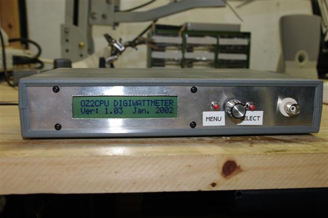
This is one of them. OZ2CPU in Copenhagen, Denmark has published plans and hex code for an RF wattmeter based on an Analog Devices AD8307 log amplifier.
The software in the PIC interprets the voltage output and displays useful information on a 2x16 LCD display. I have updated the firmware on this unit to 1.04.
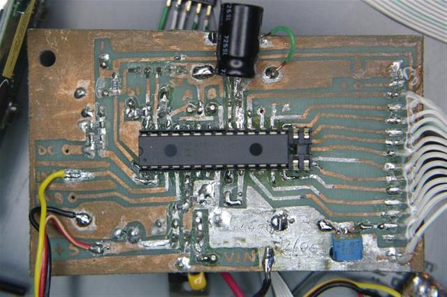
This picture was taken with my Pentax DSLR through my 10x magnifier -- you know -- the kind that has the fluorescent tube around the lens -- makes for up-close illumination without shadow. Maybe one of these days I'll actually invest in a ring flash for the camera.
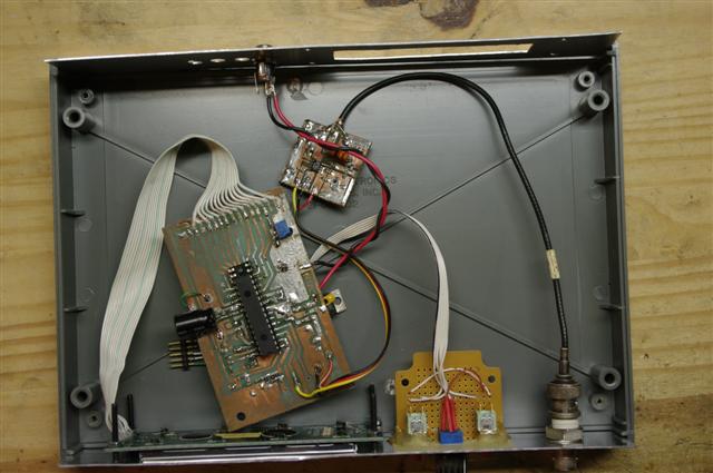
And I ended up with this kludgy device -- which amazingly seems to work! In conjunction with a -40dB attenuator, and the device can handle an offset of any value attenuator, will measure power levels from basically nothing to over 100 watts.
This is the first of two that I plan to build. The second unit I am using a PCB I etched using the toner-transfer method. I also have a Narda directional coupler which will interface with the A and B inputs on this unit to allow for accurate measurement of SWR. If that isn't enough, the device also has serial output to connect to a PC to record the measurements.
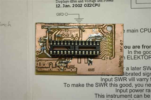
This board, as you can see, was etched in 2007. It has been sitting in one of my project boxes waiting for some time where I can get around to working on the project. I need a few parts from digikey to finish this project. I also need to etch the sensor boards. One of these days...
Mon Dec 31 20:25:04 CST 2012
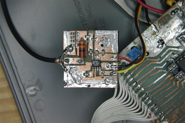
Over Christmas break I finally got a few hours to work on a new version of the project, closer to what was published in Elektor magazine. This version has two AD8307 log amplifier chips with a slightly different layout.
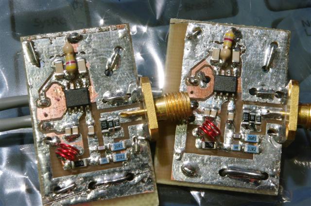 Above are the two boards I etched before the brass RF shields were
soldered on. I'm using SMA connectors on this version. No, I did
not have a 47K SMT resistor in my junkbox (everything else was in
my junkbox!) so I used a 1/4W leaded part. Not in the RF path so
no big deal I suppose.
Above are the two boards I etched before the brass RF shields were
soldered on. I'm using SMA connectors on this version. No, I did
not have a 47K SMT resistor in my junkbox (everything else was in
my junkbox!) so I used a 1/4W leaded part. Not in the RF path so
no big deal I suppose.
I also have a new board etched which mounts on the back of a 2x20 LCD. There was a version prior to this but the 2x20 LCD that I had was damaged somewhere and didn't display the characters at the end which made it really clunky. That's what you get for cut-rate old-stock LCD displays, I guess.
This page last modified Mon Dec 31 20:25:01 CST 2012 by timc!