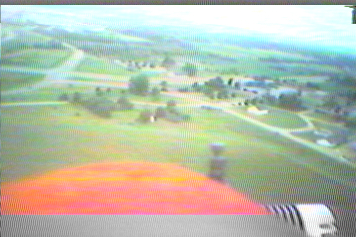
Video capture -- looking over the nose through prop arc, cylinder head is on the right.
|
MPEG video clip of a landing (3.7MB) Ok, so I'm building a Tsunami. One of the features is that the canopy extends well over the wing CG. Hmmm -- digital camera? I've already done that. Well-- what about video? X10 (www.x10.com) has some tiny-tiny 2.4 GHz video cameras that they're selling for way cheap. They're tiny. And powerable by 4.8 volts. But -- to do that, you'll need to acquire the battery pack to get the step-up circuit board unless you want to build your own. (Note about the X10 company -- If you want some of their hardware for cheap, join the email list and wait a couple days (or a week or two, you're only halfway serious about this, right?) for a bargain, then buy.) In any case, I bought one and hacked it for the plane.
First Impression
Other info
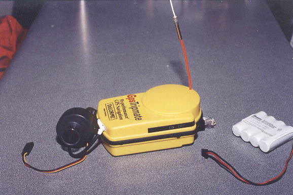
How to ID -- morse code on the audio output. Where to get the CW ID? What about ... using an APRS-MIM module on the audio output. As long as that's there, how about attaching a small GPS? And gee, what about using those 8 channels of telemetry! So, there's my project:
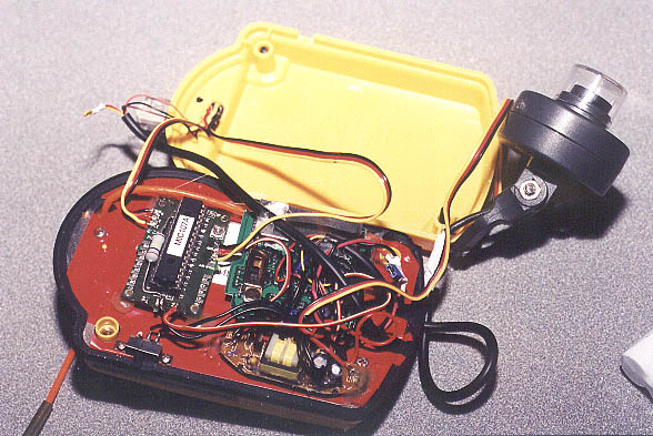
Progress 13 November 2000: I added another RCA jack and DPDT switch to my video camera to take the composite input from the 2.4GHz receiver. The switch selects either lens or external video. If I were really clever, I would have just stuffed the 2.4GHz receiver in the videocamera handhold molding. 20 November 2000: Sent in the order for another APRS-MIM module. I understand that WB4APR now has a new tested supply. 04 December 2000: Received APRS-MIM module. Too bad the post office smashed the unit prior to delivery. Back to WB4APR... 26-27-28 January 2001: Received new MIM module. After a marathon session with the soldering iron, I have a DeLorme Tripmate GPS with the battery case refitted with a 2.4GHz transmitter and APRS-MIM module. I replaced the X10 transmitter antenna with a 1/4 wave antenna. I have significantly more range now, and we all know that a 1/4 wave antenna isn't a stellar antenna as far as performance goes. I have some more modifications and enhancements to add, but the case shuts, and it works as I'd hoped. I've include an RJ-45 jack on the unit so that I can hook the sucker up to a standard 2M radio for regular APRS use, to a terminal for either configuration or straight GPS output. I had one sneaky problem while troubleshooting. The APRS-MIM module worked flawlessly while testing prior to placing it with the rest of the junk. Then I put it with the rest of the stuff and could no longer program the unit. Hmmm. So, out came the o-scope, and a bunch of other crap. Sometimes it would program and configure. Sometimes -- nothing. Damn. Then it occured to me that it would program if the o-scope pin was on one particular lead of the PIC chip. Or...if I was touching circuitry that was connected to that pin. So, I soldered a 1M-ohm resistor between the PIC chip pin in question and ground. 100% success now. I won't question it. Preliminary tests are giving me about 500' range for Q5 reception from the transmitter to my receiver, THROUGH my metal apartment building walls. I bet I could do better in the clear. But still, 500' with obstructions is great as far as I'm concerned. Aiming the patch antenna is critical, but I'm going to change that out as soon as I find suitable material with which to make a really short loop yagi for 2.4GHz. 15 July 2001: Theory moves into practice -- I finally got the plane in the air with the video. KB9UZK ran the receiver and pointed the antenna. I built a 10-element loop yagi for 2.4 ghz -- this might not be the best antenna for this. Well, since I built it, it'll be easy to take elements off, and I have four more elements I could still add if that's necessary. Range tests, however, are in order.
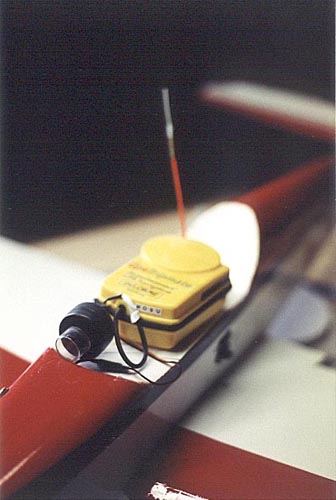
X10 cam and GPS mounted in Tsunami. I use Velcro. No, it hasn't fallen off. Yes, I leave the canopy off during flight. No, it doesn't get greasy, all of the exhaust goes under the plane. August 2001: Too hot to fly. Ordered a 2.4GHz preamp from Down East Microwave. Waiting for it to arrive. Hoping that I can get away with a bit less antenna with a preamp. After all, how sensitive can this video receiver be? 29/30/31 August 2001: Down East Microwave 13ULNAK 2.4GHz preamp completed! Don't order the kit if you can't do surface mount. Went together and tuned up exactly like they said. What else could you want??? Mounted the preamp under the circuit board in the receiver; there's just enough room. No real tests, but with the TX in the basement, and the RX upstairs, I didn't even need an antenna for Q5 reception. How's that? My 802.11b wireless hub did cause some interference, but interestingly, the loop yagi could eliminat theat completely. Also building a crossed-dipole for 2.4GHz for an antenna. Hoping this proves to be a reasonable combination. Also have the voltage regulators, and most importantly, the coaxial power plugs to run everything from 12 volts. September 2001: Somewhere in here, I got some flying done. Receive antenna was changed to a crossed dipole with reflector, voltage regulator for the camera has been built. (I didn't know an LM7805 could get that hot...) Results are much better, Q4-Q5 within a 45 degree arc of the antenna. No more playing duckhunter with a loop yagi. Next tests will be done with me wearing the receiver/antenna around my neck with a strap. That should get me continuous good coverage instead of good coverage only while I pass through the antenna arc. 14 April 2002: 1-Watt amplifier based on the RFMD 2126 is now complete and in-line. I don't have any real test equipment, but I show a higher field strength now. Input power to the amp suggests that I might have only 1/8 watt output. Input power to the TX suggests I had much less than that. So, this is probably just fine. I still haven't done anything with a noise bridge in terms of trying to tune the antenna, but them's plans in the works. I am also now working on going over to a 12V 2Ah source rather than a 4.8V 450mAh source. 25 August 2002:Yesterday marked only the second time the plane was out this year, and for that matter, without the video transmitter. That's OK -- it's an ongoing project. I've been spending a LOT of time making test equipment for 2.4GHz. Why? I can't afford anything with an HP logo on it, and I need some way to test stuff. A good deal of my information has come from these guys in Green Bay, Wisconsin. I've built the 2.4GHz prescaler, a power meter, a field strength indicator, modified a 2.4GHz noise source, and built a return-loss bridge. There really isn't a good source of information on these cameras. Nobody with any real knowledge of RF seems to have taken a serious look at this hardware, and there are a lot of turkeys who have done an excellent job at reaching the pinnacle of mediocrity with this hardware. A DC-DC converter to make your 9V battery 12V and then let the internal 78L08 re-regulate it down to 8 volts? Hello? WTF? Whatever. So, initial conclusions are that the input to the RFMD2126 is a bit low for optimal output. I might end up installing a MMIC or something before the amp. I'm still awful damn tempted to open the metal covering on the X10 transmitter to see if there's a n-dB pad in there. The schematic suggests not. But if it takes a hacksaw to open something, you'll be needing a hacksaw to figure out why. Still, some honest measurements and numbers are in order. And what should be on-order is one of these things. Takes the GPS data and sticks it on the screen. About $120. Will be well worth the gee-whiz factor when I've got power coming out of this sucker. Stuff to be done:
Comments welcome. More later. last modified Sun Aug 25 01:25:37 CDT 2002 by timc! |