|
|
|
Homework 3 // Due at lecture Feb 23, MonPrimary contact for this homework: Mengmeng Chen [mchen at cs dot wisc dot edu] You must do this homework alone. Please staple multiple pages together. Problem 1
Draw a logic circuit corresponding to the following logic expression. You must use four NOT gates, three 2-input OR gates and two 2-input AND gates. Problem 2
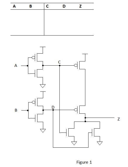
For the transistor-level circuit in Figure 1, fill in the truth table. What is Z in terms of A and B?
Problem 3Fill in the truth table for the logical expression NOT(A) AND NOT(A OR B). 
Problem 4
For this question, refer to the figure below.
Problem 5How many different memory locations can we have with 32-bit address? If the memory is byte-addressable, how many bits does the memory hold? Problem 6
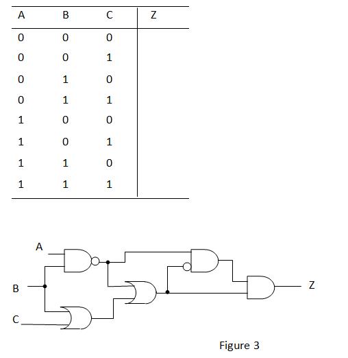
Given the logic circuit in Figure 3, fill in the truth table for the output value Z.
Problem 7
A full binary adder, described in Figures 3.14 and 3.15 on page 62 of the book, adds three inputs A, B, and Cin and produces two outputs, the sum S and the carry out Cout. These can be combined into a four-bit binary adder as shown in Figure 3.16 on page 63. If A and B are four-bit unsigned binary numbers, 0111 and 1011, complete the table below for each of the sum and carry bits. Check your answer by adding the decimal values of A and B and comparing the sum with S. Are the answers the same? Why or Why not?
Problem 8
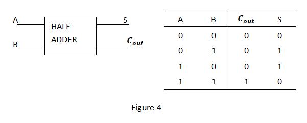
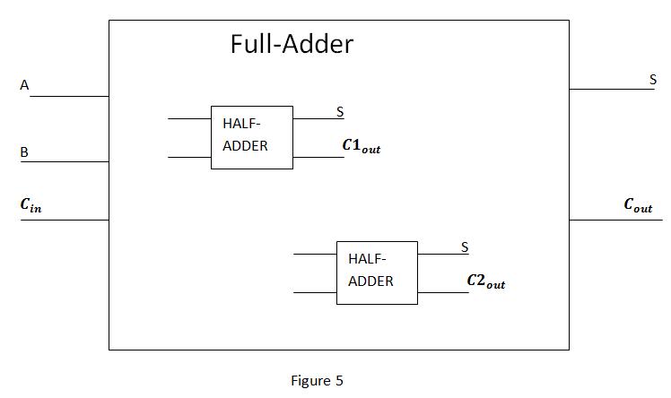
A half-adder is another kind of logic circuit that can perform binary addition. The difference between a full-adder and a half-adder is that a half-adder does not take the carry-in as input. A typical half-adder is illustrated in Figure 4. One way to build a full-adder is to use two half-adders as basic building blocks. Now try to build a full-adder by drawing the necessary connections in Figure 5. (Note that you need one more 2-input gate (‘AND’ or ‘OR’) to finish the job. Feel free to choose one and add it in the box.)
|


