The "Meet Over All Paths" Solution
The MOP solution (for a forward problem) for each CFG node n is defined as follows:
- For every path "enter → ... → n", compute the dataflow fact induced by that path (by applying the dataflow functions associated with the nodes on the path to the initial dataflow fact).
- Combine the computed facts (using the combining operator, ⌈⌉ ).
- The result is the MOP solution for node n.
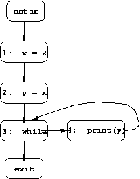
For instance, in our running example program there are two paths
from the start of the program to line 9 (the assignment k = a):
Combining the information from both paths, we see that the MOP solution for node 9 is: k=2 and a=4.
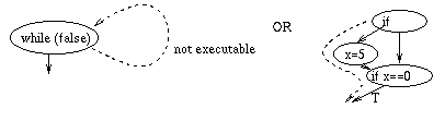
It is worth noting that even the MOP solution can be overly conservative (i.e., may include too much information for a "may" problem, and too little information for a "must" problem), because not all paths in the CFG are executable. For example, a program may include a predicate that always evaluates to false (e.g., a programmer may include a test as a debugging device -- if the program is correct, then the test will always fail, but if the program contains an error then the test might succeed, reporting that error). Another way that non-executable paths can arise is when two predicates on the path are not independent (e.g., whenever the first evaluates to true then so does the second). These situations are illustrated below.
Unfortunately, since most programs include loops, they also
have infinitely many paths, and thus it is not possible to compute
the MOP solution to a dataflow problem by computing information
for every path and combining that information.
Fortunately, there are other ways to solve dataflow problems
(given certain reasonable assumptions about the dataflow
functions associated with the CFG nodes).
As we shall see, if those functions are distributive,
then the solution that we compute is identical to the MOP solution.
If the functions are monotonic, then the solution may
not be identical to the MOP solution, but is a conservative
approximation.
The alternative to computing the MOP solution directly, is to
solve a system of equations that essentially specify that local
information must be consistent with the dataflow functions.
In particular, we associate two dataflow facts with each node n:
One question is whether, in general, our system of equations will
have a unique solution.
The answer is that, in the presence of loops, there may be multiple
solutions.
For example, consider the simple program whose CFG is given below:
The equations for constant propagation are as follows (where ⌈⌉ is
the intersection-like combining operator):
The solution we want is solution 4, which includes the most
constant information.
In general, for a "must" problem the desired solution will be the
largest one, while for a "may" problem the desired solution will be
the smallest one.
Solving a Dataflow Problem by Solving a Set of Equations
These n.befores and n.afters are the variables of our equations,
which are defined as follows (two equations for each node n):
In addition, we have one equation for the enter node:
where p1, p2, etc are n's predecessors in the CFG (and ⌈⌉
is the combining operator for this dataflow problem).
These equations make intuitive sense: the dataflow information that
holds before node n executes is the combination of the information
that holds after each of n's predecessors executes, and the information
that holds after n executes is the result of applying n's dataflow
function to the information that holds before n executes.
enter.after = empty set
Because of the cycle in the example CFG, the equations for
3.before, 3.after, 4.before, and
4.after are mutually recursive, which leads to the following
four possible solutions (differing on those four values):
1.before = enter.after
1.after = 1.before with x mapped to 2
2.before = 1.after
2.after = if x is constant c in 2.before then 2.before with y mapped
to c, else 2.before with y not mapped to anything
3.before = ⌈⌉( 2.after, 4.after )
3.after = 3.before
4.before = 3.after
4.after = 4.before
Using the simple CFG given above, write the equations for live-variable analysis, as well as all possible solutions. Which is the desired solution, and why?
Many different algorithms have been designed for solving
a dataflow problem's system of equations.
Most can be classified as either iterative algorithms
or elimination algorithms.
These two classes of algorithms are discussed in the next two sections.
Most of the iterative algorithms are variations on the following
algorithm:
Iterative Algorithms
Set enter.after = init. Set all other n.after to the
value v such that for all values d in the domain of dataflow
facts, ⌈⌉(v, d) = d. (When we consider the lattice model for
dataflow analysis we will see that this initial value is the
top element of the lattice.)
Initialize a worklist to contain all CFG nodes except enter and
exit.
While the worklist is not empty:
Remove a node n from the worklist.
Compute n.before by combining all p.after such that
p is a predecessor of n in the CFG.
Compute tmp = fn ( n.before )
If (tmp != n.after) then
Set n.after = tmp
Put all of n's successors on the worklist
Run this iterative algorithm on the simple CFG given above. (The n.afters should be initialized to a mapping that maps all variables to all values. This means that if the node n removed from the worklist in step 3 has a predecessor p that has not yet been processed, p.after will have no effect on the value computed for tmp. Therefore, when you compute tmp in step 3, you can simply ignore the "after" values for nodes that haven't been processed yet.) Run the algorithm again on the example CFG from the examples section of the notes.
This algorithm works regardless of the order in which nodes are
removed from the worklist.
However, that order can affect the efficiency of the algorithm.
A number of variations have been developed that involve different
ways of choosing that order.
When we consider the lattice model, we will revisit the question
of complexity.
For now, consider the specific case of constant propagation.
It is not hard to see that the sizes of the "after" mappings
can only decrease as the algorithm progresses.
In particular, after being processed once, a particular n.after
can have at most one mapping for each variable.
If node n is processed again, the number of mappings in n.after
can only decrease.
Thus, for each node n, n.after can change at most V times, where V is the
number of variables in the program.
Each time n.after changes, all of its successors are put onto the
worklist.
If a node n has k predecessors, and the values of all of their
"after" mappings change V times, then n
will be put onto the worklist at most V * k times.
In the worst case, a node can have O(N) predecessors, where N is the
number of CFG nodes, so the worst-case running time for the algorithm
is O(N2 * V).
If we assume that the number of edges in the CFG is O(N), which is
true of programs in practice, then the worst-case time is O(N * V).
Elimination algorithms work in two passes.
The first pass applies a sequence of transformations to the CFG
that reduce it to a single node.
At the same time, the dataflow functions associated with the
nodes of the CFG are combined to provide dataflow functions
for the nodes of the reduced CFG (finishing with a single
dataflow function that captures the effect of the entire
program on the initial dataflow fact).
The second pass reverses the process;
it applies the transformations in reverse order to expand
from a single-node CFG to the original CFG.
At the same time, the dataflow functions associated with
the nodes of each successive CFG are applied.
When the process finishes, a solution to the dataflow
problem has been computed for all nodes of the original CFG.
A number of elimination algorithms have been defined.
We will consider only the original algorithm, interval analysis,
due to Allen and Cocke (see the class reading list).
They defined their algorithm for two specific dataflow problems:
reaching definitions and live-variable analysis.
The technique can be applied to a more general class of dataflow
problems (as long as the appropriate operations can be performed
on the dataflow functions).
Here we give the algorithm for reaching definitions.
The same algorithm can be used for any forward GEN/KILL problem
for which the combining operator (the meet operator) is set union.
This is because the dataflow functions for all such problems can
be defined the same way:
fn(S) = (S intersect NOT-KILL(n)) union GEN(n),
and because the interval analysis is defined in terms of the NOT-KILL
and GEN sets for each CFG node.
(So if we want to use the interval analysis for a different
problem, we would just substitute the appropriate NOT-KILL
and GEN sets for the initial CFG.)
Interval analysis works by dividing the CFG into a set of intervals
(defined below).
Then a new (smaller) CFG is formed by collapsing each interval into
a single node, while computing the GEN and NOT-KILL
sets for the new node in terms of the sets associated with the nodes
in the interval.
An interval I of a CFG is a set of nodes with the following
properties:
Input: the interval head node h.
I(h) = { h }
Note that a node (other than h)
is added to interval I only after all of its
predecessors have been added to I.
This order in which nodes are added to an interval (called
interval order) is important, as we shall see.
Using the algorithm given above as a subroutine, we can partition
all of the nodes of a CFG into a set of disjoint intervals as
follows:
Input: A CFG
IntervalSet = empty set
Use the algorithm given above to compute the intervals for
the example CFG in the
examples
section of the notes.
Once a CFG's set of intervals has been computed, a new CFG is
created by collapsing each interval into a single node.
There is an edge in the new CFG from node j to node k (for
j != k) iff
there was an edge in the original CFG from a node in the interval
represented by j to a node in the interval represented by k (note
that the second node must be the interval head).
The interval-analysis algorithm creates a sequence of CFGs by
computing intervals, collapsing them, computing intervals in
the new CFG, etc.
The sequence for the example CFG given above is shown below.
Elimination Algorithms
Intervals
Below is an algorithm that, given a node h, computes I(h),
the set of nodes that is the largest interval with head h.
The figure below shows a CFG, and lists the nodes in
I(h) for four different nodes h.
Algorithm for computing a maximal interval with head h
Output: set I(h): the nodes in the maximal interval
with head h.
while there is a node n such that:
n is a successor of some node in I(h), and
add n to I(h).
n is not in I(h), and

The intervals listed for the example CFG above are exactly those
that would be identified by this algorithm.
Algorithm for partitioning a CFG into intervals
Output: IntervalSet, a set of intervals
Auxiliary: H, a set of interval heads
H = { enter }
while H is not empty:
remove a node h from H
compute I(h) using the above algorithm for computing a
maximal interval
add I(h) to IntervalSet
add to H all nodes n such that:
n is not already in H, and
n is not in I(h), and
n has a predecessor in I(h)
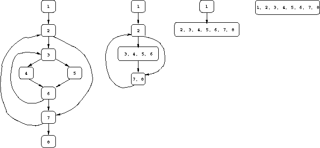
Use the algorithm given above to compute the sequence of CFGs for the example program in the examples section of the notes.
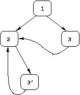
An important question is whether all CFGs can be collapsed to
a single node using this approach.
The answer is no.
The CFGs that can be collapsed are called reducible
CFGs, and it has been shown that all non-reducible CFGs include
a subgraph of the form:
In practice, irreducible CFGs are rare.
Furthermore, a technique called "node-splitting" can be
applied to transform an irreducible CFG to a reducible one, in such
a way that the solution to a dataflow problem computed for the
transformed CFG provides a solution for the original CFG.
The transformed version of the irreducible CFG shown above
is shown below.
Each time interval analysis collapses an interval I with
head node h to a single
CFG node, it computes GEN and NOT-KILL sets for the
new node using the algorithm given below.
Actually, the algorithm computes these sets for edges:
if I and J are two intervals (that will be represented in the collapsed
CFG by nodes I and J), and there will be an edge in the collapsed CFG
from I to J, then we need to compute GEN(I, J) and NOT-KILL(I, J).
The need for computing GEN and NOT-KILL for edges (rather than nodes)
is as follows:
In the original CFG, whether a node n represents an individual statement
or a basic block, the same statement or statements execute every time
n is reached, so the same GEN and NOT-KILL sets apply.
In a "collapsed" CFG, however, nodes represent intervals, and an
interval is not necessarily a straight-line, single-exit sequence
of instructions.
Consider a node that represents an interval I, and that has successors
J and K in the collapsed CFG.
Execution may follow different paths through I to get to J and to K;
and those different paths may have different GEN and NOT-KILL sets.
Therefore, we must compute GEN and NOT-KILL sets for the edges I→J and
I→K, not just GEN and NOT-KILL sets for I.
For example, consider the following (incomplete) CFG:
Note that for a node n of the original CFG, for every successor s
of n, GEN(n,s) and NOT-KILL(n,s) are simply the original GEN and
NOT-KILL sets for n.
The interval-analysis algorithm processes each node in the interval in
interval order (the order in which the nodes were added to the
interval).
In order to compute the GEN and NOT-KILL sets
for the interval, the algorithm first computes two sets for each
edge n→m, such that node n is in the interval:
Here is the algorithm that is the heart of interval analysis pass 1:
Algorithm for computing GEN, NOT-KILL, and R sets for an interval I
Input: Interval I with head h (with GEN and NOT-KILL sets for every edge)
for each edge h→m (whether or not m is in I):
// COMPUTE GEN AND NOT-KILL SETS FOR THIS INTERVAL'S OUTGOING EDGES
Pass 1 of interval analysis first computes
the sequence of CFGs G1, G2, ..., Gm.
It then applies the algorithm
given above to each interval in G1, then to each interval in
G2, etc., to compute GEN and NOT-KILL
sets for the outgoing edges of each interval in each CFG, and the R set
for the head of each interval in each CFG.
Algorithm for interval analysis pass 1
Input: A CFG.
Apply the algorithm for partitioning a CFG into intervals to the given CFG.
Apply the algorithm given above to the example from the
examples
section of the notes, for the reaching definitions problem.
The second pass of interval analysis goes back through the
sequence of CFGs produced by the first pass in reverse order.
For each CFG in the sequence, it computes the
dataflow solution for that CFG's nodes.
In particular,
for each node n in each CFG in the sequence,
pass 2 computes n.before, the set of definitions that may reach node n.
For the single interval I in the last CFG in the sequence,
the dataflow solution is simply the initial dataflow fact (init);
i.e., pass 2 starts by setting I.before = init for the single interval
I in the last CFG (for reaching definitions, init is the empty set).
Pass 2 then makes use of the following algorithm:
Algorithm for computing before sets for the nodes of an interval I
Input: Interval I with head node h (with R(h) defined by pass 1),
and dataflow fact I.before
h.before = I.before union R(h)
Note that the use of interval order is critical: it guarantees that,
for every predecessor x of n, After(x,n) will be available when n is
processed.
Pass 2 of interval analysis applies the algorithm
given above to the single interval in Gm, then to each interval in
Gm-1, then to each interval in Gm-2, etc., to compute n.before
for each node n in each CFG.
Algorithm for interval analysis pass 2
Input: A sequence of CFGs G1, G2, ..., Gm,
and the GEN, NOT-KILL, and R sets for each interval I in each CFG.
for (the single) interval I in Gm set I.before = init
Apply interval analysis pass 2 to the running example.
The notation used above in defining interval analysis for reaching
definitions is not exactly the same as the notation used in the Allen/Cocke
paper.
In particular:
Return to
Dataflow Analysis table of contents.
Go to the previous
section.
Go to the next section.
Irreducible CFGs

Interval analysis pass 1
            [1] x = 0
                 |
                 v
            [2] if (...)
               /        \
              v          v
          [3] y = 3    [4] x = 2
              |            |
              v            v
  [5] while (...) <--+    [6] while (...) <--+
         /     \     |           /    \      |
        /       \    |          /      \     |
Note that nodes 1, 2, 3, and 4 will form one interval I1, and that
nodes 5 and 6 will be the heads of two other intervals I2 and I3
(because they have incoming back edges, as well as the edges from
nodes 3 and 4, respectively).
In terms of reaching definitions, interval I1 generates three:
those at nodes 1, 3, and 4.
However, the definitions at nodes 1 and 3 only reach the start of
interval I2 (not the start of interval I3), and the definition
at node 4 only reaches the start of
interval I3 (not the start of interval I2).
Therefore, we cannot define a single value GEN(I1);
instead, we must define: GEN(I1, I2) = {(x, [1]), (y, [3])}
and GEN(I1, I3) = {(x, [4])}.
(And similarly for the NOT-KILL sets of interval I1.)
It also computes the set R(h) for header node h;
the set of definitions in the interval that can reach h via a cyclic
path that starts and ends at node h.
Output: GEN(I,J), NOT-KILL(I, J) for all successors J of I, and R(h)
Auxiliary: for each node n in I, for each edge n→m, P(n,m) and D(n,m)
P(h,m) = NOT-KILL(h,m)
for each node n in I-{h} in interval order:
D(h,m) = GEN(h,m)
PRE = the union of P(x,n) for all predecessors x of n
R(h) = the union of D(n,h) for all predecessors n of h in I
DEF = the union of D(x,n) for all predecessors x of n
for each edge n→m (whether or not m is in I):
P(n,m) = PRE intersect NOT-KILL(n,m)
D(n,m) = (DEF intersect NOT-KILL(n,m)) union GEN(n,m)
for each interval J that is a successor of I in the next CFG:
PRE = the union of P(n, h(J)) for all edges n→h(J) s.t. n is in I
DEF = the union of D(n, h(J)) for all edges n→h(J) s.t. n is in I
NOT-KILL(I,J) = PRE
GEN(I,J) = (R(h) intersect PRE) union DEF
Output: A sequence of CFGs G1, G2, ..., Gm,
the GEN and NOT-KILL sets for the outgoing edges of
each interval I in each CFG, and the R set for each interval I
in each CFG.
while the current CFG has more than one interval:
create the next CFG in the sequence by collapsing all intervals in the
current CFG;
for each CFG G in the sequence:
apply the algorithm for partitioning a CFG into intervals to the new CFG
for each interval I in G:
apply the above algorithm for computing GEN, NOT-KILL, and R sets to I
Interval analysis pass 2
Output: n.before for every node n in I
Auxiliary: for each node n in I, for each edge n→m, After(n,m)
for each edge h→m (whether or not m is in I):
After(h,m) = (h.before intersect NOT-KILL(h,m)) union GEN(h,m)
for each node n in I - {h} in interval order:
n.before = the union of After(x,n) for all edges x→n
for each edge n→m:
After(n,m) = (n.before intersect NOT-KILL(n,m)) union GEN(n,m)
Output: For each node n in G1, the set n.before
for each CFG in the sequence in reverse order
for each interval I in the current CFG
apply the above algorithm for computing "after" sets to I, I.before
Notes on the Allen/Cocke paper
In addition, the algorithm for Phase 1 presented in the paper
has a minor mistake in the computations of the NOT-KILL and GEN sets for
the outgoing edges of an interval (note also that in the paper this is
done at the beginning of Phase 1 for the current CFG -- except when
the current CFG is the first CFG -- rather than at the end of Phase 1,
as is done in these notes).
The mistake in the paper's algorithm is to ignore the fact that
in general there may be more than one edge n → h(J), where n is
a node in interval I.
Because of this oversight,
the NOT-KILL and GEN sets (called the PB and DB sets) for the edge
I→J given in the paper each involve just a single edge from a node in
I to the head of J;
the correct definition (given in these notes) takes into account
all edges from a node in I to the head of J.