Page Contents
- Starting the Modeller
- The Main Window
- Creating a Model From Scratch
- Testing the Dynamics Interactions
- Automatically Bounding the Entire Model
Starting the Modeller
The Modeller is started with the following command line:
java berkeley.cs.dmc.dmod.Main
There are no command line arguments. The modeller should be
started in the directory containing all your models and dynamics.
Like all tools in the DMC package, it is assumed that the DMC classes
are already in your CLASSPATH.
The Main Window
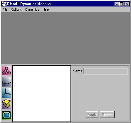
This is the main window of the DMC modeller. The actual appearance may vary slightly from platform to platform. The main window is divided into three sections: the upper dark gray area is the model view, the lower left white area is the model tree view, and the lower right area is the tree node area. In the model view area of the window, the model in its current state is rendered. A simple crystal ball like interface allows for simple navigation around the model. By default the Y axis is up, and the view is centered around the origin. The tree view area is where the model hierarchy is displayed. Nodes may be dragged and dropped into place from the left toolbar, and later moved around within the tree view. The components on the left are the tree nodes of the DMC system. They are, from top to bottom:
The tree node area contains all information of the node selected in the tree view area. After the fields values have been modified, the Apply button applies the changes. The Delete button will delete the node from the tree. |
Creating a Model From Scratch
In the following sections we will demonstrate how to use the
modeller by going through the step by step construction of a
"Tilt-A-Whirl" model. The fully constructed model is available from
the examples page.
1. Adding a VRML PROTO
|
The DMC Modeller contains a full VRML97 parser, but can only render a limited subset of the VRML97 nodes. What this translates into is that any valid VRML model will work in the DMC Modeller, but it may not be completely displayed. The DMC Modeller is only a modeller in the extent that it connects models together into a larger model. For creating detailed models there are many publicly and commercially available modellers. Tilt_Platform.wrl, the VRML model included here, and many of the other models used in the examples were created using SCED. The source for Tilt_Platform.wrl is available here. |
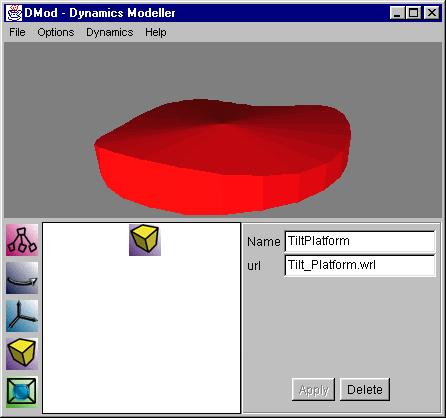 The first step is to add the Tilt Platform to the model by
dragging a VRML Model node from the left toolbar to the tree
view area. After it is dropped into place, it is automatically
selected, and we type in the node's name and the URL of the model.
The URL in this case is a relative URL of a VRML97 model located in
the directory we started the modeller in. Abosolute file names and
URL's are also understood.
The first step is to add the Tilt Platform to the model by
dragging a VRML Model node from the left toolbar to the tree
view area. After it is dropped into place, it is automatically
selected, and we type in the node's name and the URL of the model.
The URL in this case is a relative URL of a VRML97 model located in
the directory we started the modeller in. Abosolute file names and
URL's are also understood.
2. Adding Rotations, Transforms and Variables
|
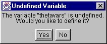
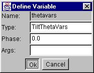
After the Apply button is pressed a dialog box pops up asking if we'd like to define the variable.
After answering yes, we define the variable to be of type "TiltThetaVars" and to have an initial phase of 0, in the next dialog that pops up.
|
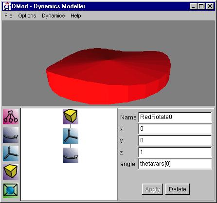 In the next step we've added two nodes in a similar fashion to how we
added the Tilt_Platform in the first step. The translation
node is dragged over the tilt platform model node and set to a
translation of (0,0,1). The rotation node, RedRotate0, is then
added and rotates about the z-axiz with an angle defined by the
variable thetavars[0].
In the next step we've added two nodes in a similar fashion to how we
added the Tilt_Platform in the first step. The translation
node is dragged over the tilt platform model node and set to a
translation of (0,0,1). The rotation node, RedRotate0, is then
added and rotates about the z-axiz with an angle defined by the
variable thetavars[0].
 The type of the variable is name of a Java class that implements
3. Completing the Model
|
The rest of the model is built similarly. For the TiltAWhirl model
we have layed out a tree heirarchy as the picture.
Similarly each branch is: a rotation about the platform, a tilt along the platform, a fixed translation to the edge of the platform, a tilt around the edge of the platform, a bounding node for the car and car platform, a fixed rotation on the normal, and a car platform alongside a rotated car. The dynamics are hooked in with one variable controlling the rotation about the Tilt_Platform (TiltThetaVars), a closed-form car tilt on the platform (TiltCarVarsClosed), and a compiled dynamical system for the cars rotation on its platform (TiltCarSystem). |
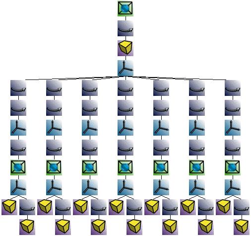 The picture looks more complex than it actually is. Each of the seven
long branches are the series of transformations required for a single
chair. Tracing the nodes from the top down, there is: the bounding
volume for the entire model, a fixed rotation, the Tilt_Platform from
step 1, a translation up for all the chairs, and then the individual
chair branches.
The picture looks more complex than it actually is. Each of the seven
long branches are the series of transformations required for a single
chair. Tracing the nodes from the top down, there is: the bounding
volume for the entire model, a fixed rotation, the Tilt_Platform from
step 1, a translation up for all the chairs, and then the individual
chair branches.
Testing the Dynamics Interactions
|
To stop the system at anytime, use the Stop! option in the Dynamics menu. The variables will be left in the state that they were stopped in, and no further updates will occur until the model is run again. This feature is very useful for seeing how the model will look when it is finally converted to VRML. |
 To test the interaction between the VRML models and the dynamics,
select in the Run! option in the Dynamics menu. This
will attempt to load the classes associated with the variables in the
system and run them in real time. The model can continue to be
modified while the dynamics are running. So, besides the CPU time and
the flakiness of the Java VM's, you can feel to leave it running while
you work out the kinks of the model. You should, however, for those
same reasons, feel compelled to save often. :-)
To test the interaction between the VRML models and the dynamics,
select in the Run! option in the Dynamics menu. This
will attempt to load the classes associated with the variables in the
system and run them in real time. The model can continue to be
modified while the dynamics are running. So, besides the CPU time and
the flakiness of the Java VM's, you can feel to leave it running while
you work out the kinks of the model. You should, however, for those
same reasons, feel compelled to save often. :-)
Automatically Bounding the Entire Model
|
It is necessary to have a bounding volume for the dynamics to be culled by the DMC runtime system. Using the modellers Bound Model... option after running the system for a few seconds (or minutes, depending on the model) is an easy way of adding tight bounds to meet this requirement. |
 While the system is being built and while the model is being run as
per the previous section, the modeller is constantly updating the
bounds of the entire model. These bounds can be made visible by
selecting the View Bounds option in the Options menu.
They can also be automatically inserted at the root of the model with
the Bound Model... option in the same menu.
While the system is being built and while the model is being run as
per the previous section, the modeller is constantly updating the
bounds of the entire model. These bounds can be made visible by
selecting the View Bounds option in the Options menu.
They can also be automatically inserted at the root of the model with
the Bound Model... option in the same menu.