How it works
 OK
here's the simplified analogy of the real guitar and laser guitar. We knew
at first it will be tough to do it with all lasers (no push buttons) due
to the price of laser components we would need to accomplish such task.
Left part, supposedly the real guitar has blue
lines to represent the frets, and black lines to represent the strings.
The laser counterpart, has push buttons (labeled a1... c3) to substitute
the top 3 frets of guitar, and red lines as
the laser strings. Sorry for the number of strings (supposed to be 6 for
real guitars), it's been reduced to simplify the design.
Imagine putting your fingers on leftmost string on real guitar on first, second and third fret. Then pluck the leftmost string. What will you hear ? And now release your fingers on the first and second, leaving the third one. Pluck the same string. What will you hear ? If you guessed it will sound the same, you're right, that's just basic of physics. The same thing will happen to laser guitar, suppose you push buttons a1, b1, and c1, then pluck the leftmost string, it will sound the same as if you just push c1 alone and pluck leftmost string!
Now, in real world, you would "tune" your guitar strings to get a good frequency. With laser guitar, however, you can change it to whatever note you want and it's always sharp to the frequency. And the good news, it doesnt have to be in order. Example: usual guitar's 3rd string would have D for free string, then D#, E, E# for 1st, 2nd, 3rd fret. You can do the same with laser guitar. But the difference is simple: you can assign C, D, E, F if you want to those "fret buttons", or may be G, D, C, F, or whatever. It's completely software controlled. Of course this is not helpful for experienced guitar player but for non-guitar players (like us) it made a very nice introduction to guitar.
Schematics
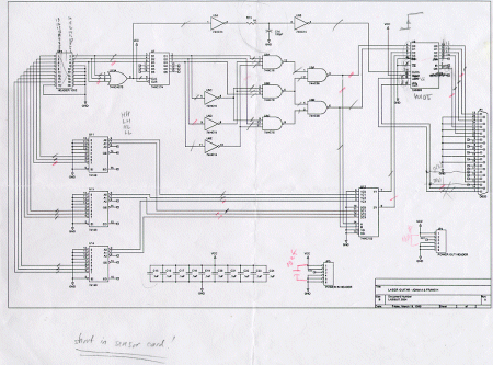
Here is one almost complete
circuit design. Hey, can't give you the whole thing, you know.
WARNING:
do not try to implement this at home, it will generate excessive heat a.k.a
smoking. There is some short from VCC to GND in this schematic. Click for
larger clearer image.

Part details
Priority encoder
We're using standard 4x2
priority encoder. This is to implement the "fret" part.
Buffer used
We're using 4 x 4 FIFO buffer
with input ready, output ready strobe signal.
How it works is like this.
Data can only be sent to the buffer when the input ready signal is on,
and usually it takes 9 ns to process the data. When buffer is not empty,
an output ready signal is on, and then the software must grab it by sending
an active low strobe to get the FIFO put the data on its output.
Gates used
We're using those standard
74HCxx gates chips for most of it.